LocoNet
Throttle Network:
LocoNetSummary: LocoNet is the throttle network designed and used by Digitrax to communicate between throttles, command stations, boosters and other accessories. Interfaces are available to allow a computer to be connected to LocoNet. Several other DCC Manufacturers also employ LocoNet as their throttle network.
| See more Throttle Networks | |
|---|---|
| General information | |
| Common Name | |
| Used by | |
| Reference material URL | Manual Link |
| Has computer interface | Other |
| Year Released | 1996 |
| Year EOL | |
| Predecessor | |
| Successor | |
| Network Details | |
| Network Type | Peer-To-Peer |
| Number Of Max Devices | |
| Is open source | No |
History
What is LocoNet®
LocoNet® is a trademark identifying a LAN for model railroads designed and patented by Digitrax Inc. Portions of LocoNet® are covered by US Patent Number 6,275,739.
Prior to the year 2000, the system functioned at less than 20% of available message types and commands that LocoNet is designed for. LocoNet is designed for future expansion, where today's devices will still be able to process messages even if they cannot use it. It is also possible to use a computer with multiple ports to route and bridge messages across several LocoNets, expanding capacity.
LocoNet can interface with a computer via a a device such as the LocoBuffer or Digitrax's own PR3, PR4 or MS100 interfaces. For more information on interfacing a computer to your Digital Command Control system, please see Connecting your computer to DCC
Network Details
LocoNet is a networking technology that uses CSMA/CD (Carrier Sense Multiple Access/Collision Detection), similar to the Ethernet network commonly used to interconnect various network devices, such as computers, high speed modems, printers, etc., but optimized for model railroading.
- Carrier Sense: Message sync is done within the message stream as all devices on the network see all the messages transmitted. The devices also know when the network is busy.
- Multiple Access: The ability of all devices to access the network and generate messages on their own, without direction from a central controller.
- Collision Detection: When two devices try to send messages at the same time, creating a conflict, that they resolve those conflicts on their own.
- LocoNet is designed to allow operation at 100% capacity with fewer than one collision in 300 messages, less than Ethernet allows.
- LocoNet is similar to the standard ISO Network Model with pipelined multilevel protocol stacks and queues.
LocoNet Basics - An Introduction

LocoNet is part of a Digital Command Control system designed by Digitrax to connect throttles, boosters and other devices to the command station. LocoNet is a Peer-to-Peer Local Area Network (LAN) designed for very high traffic capacity and free-form wiring, future system expandability and ease of upgrade. It is a separate circuit from the track power used to run model trains.
Digitrax developed LocoNet to handle the communications between throttles, accessory decoders, and other devices that need communications with the command station. The command station processes, assembles and routes information to either the track and/or LocoNet. LocoNet allows fast two-way communications between devices not related to running the model trains.
Digitrax labels the LocoNet connections on their command stations as A and B, both are the higher current throttle type with RailSync.[1]. For programming of the command station, a throttle is connected directly to either LocoNet jack.
LocoNet B
A LocoNet jack may be identified as LocoNet B. It indicates a LocoNet Booster Connection, as part of a booster network. LocoNet B limits the current to 200mA. It is meant to connect the command station and boosters together, not power devices like throttles. Since most command stations are integrated with a booster, this connection is not common.
- The RailSync signals present are for use by the booster.
- Some command station/booster units offered by LocoNet licencees may have a LocoNet B connection.
Loconet T
LocoNet T indicates higher current available to power throttles, accessory decoders and other LocoNet devices. The T indicates a connection for the Throttle Network. Many devices have jacks which are just labelled LocoNet, which are LocoNet T connections. LocoNet T connections lack the RailSync signals the LocoNet B connections have, so some devices may not work when connected to a LocoNet T jack.
The front and side jacks on a UP5 panel are LocoNet T, and are not to be used to feed additional downstream devices.
LocoNet ID
The LocoNet ID is used with wireless throttles. The default LocoNet ID number is "00." This is not the same as the deprecated Layout ID concept used by NCE.
Any throttle connecting to a UR90, UR91 or a UR92/UR92CE Utility Radio Panel requires a valid LocoNet ID. When a throttle is connected to LocoNet it will discover and attach itself to that ID. The throttle will display rA or Ir indicating it has detected a radio or IR device, as well as the ID number. Remember, the wireless features must be enabled on the throttle for this to work.
LocoNet ID allows multiple clubs in close proximity, such as a train show, to use their radio throttles without interfering in the operations on another layout. Note that this is not the same RF interference causing problems with communications between the UR9x and the throttles. This is only to prevent commands from one layout's throttles from being accepted by another layout's receivers.
The throttle must have a battery installed to operate in this manner.
Changing LocoNet ID
It is possible to change the LocoNet ID if there are conflicts. The LocoNet ID number can be changed, either by following the instructions from Digitrax or by using the LocoNet ID tool in JMRI. After the LocoNet ID has been altered, all wireless throttles must be physically disconnected then reconnected to the LocoNet to update the LocoNet ID they connect to. Otherwise, the wireless throttle will not work. Tethered throttles are not impacted by the LocoNet ID change.
It is possible to change the ID number using an appropriate throttle if a computer is not available.
Opto Isolated Boosters
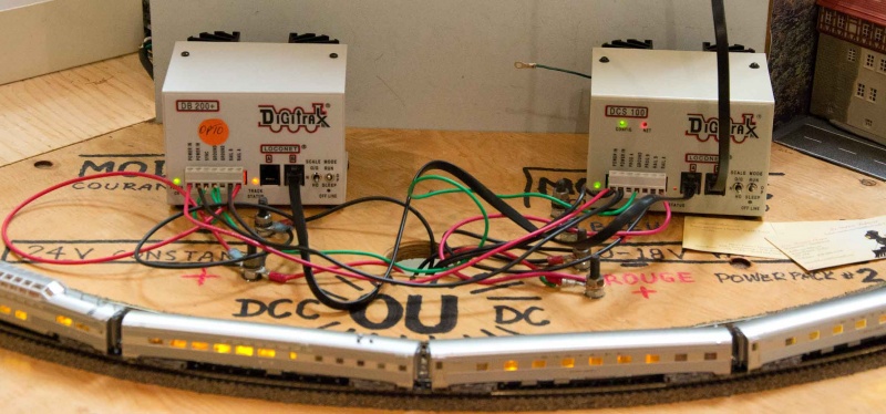
Command Station and Booster on a module set up, left one (DB200+) is an Opto Isolated Booster

Some boosters come with a label stating OPTO or OPTO-ISOLATED. What that means is the LocoNet connections on pins 3 and 4 are isolated through an optical isolation device, and the grounds (pins 2 & 5) are not connected. This prevents currents from flowing through LocoNet's ground wires to return to another booster. They are an extra cost device, and for most applications are not necessary.
As the picture shows, the modules are wired for DCC ou DC, so it is possible the modules are wired for common rail operation to accommodate analog (DC) operations. Never attempt to use analog and digital at the same time on a layout!
LocoNet Details
For more detailed information on LocoNet, see the LocoNet Personal Edition documentation from Digitrax.
As mentioned above, LocoNet is a CSMA/CD system.
- Carrier Sense - Devices monitor the LocoNet bus to decide when it is safe to transmit a message
- Multiple Access - All devices share the same LocoNet segment, so all messages are seen by all devices
- Only one device can be transmitting at a time
- Collision Detection - Devices monitor the LocoNet during transmitting, to determine if their message was corrupted by another message
- Priority based timing allows a high priority device such as track sensors to transmit their messages with with higher priority than throttles
- If two devices attempt to transmit at the same time, both messages are discarded and both devices have to retry. Devices with different priorities should not cause collisions with each other.
- A CSMA/CD network characteristic is the rate of collisions increases with network loads above 25 - 50% of the theoretical capability. For good performance load to not exceed the 10-20% of the capacity.
LocoNet operates at a speed of 16.66 kiloBaud, with one start bit, 8 data bits and a stop bit, or more than 1600 characters per second. This structure makes interfacing the LocoNet to a computer's serial port very easy. In fact, several computers may be on a LocoNet.
Being a peer-to-peer network, devices can pass messages directly to other devices without requiring a central server.
Throttles are low priority devices. Their messages are not as time sensitive as those of an occupancy detector. The system will increase their priority as transmission failures increase until the message is successfully sent. The priority is then reset to its normal priority.
More devices, more traffic. Every device that wants to talk waits a specified amount of time after the last message before attempting to send a message. After the wait time expires, another slice of time is used to determine priority: High priority devices get the first chance, low priority devices must wait longer before attempting a transmit.
The LocoNet system is a different from the NCE Cab Bus, which is a polled system, meaning "speak when spoken to". As more devices are added to a polled system, response times decline as it takes longer to poll a specific device. The system will also poll for undiscovered devices, requiring additional time to add or remove devices from the queue.
LocoNet Power
The LocoNet system has the following voltages and currents:
- The command station has a 15mA pull-up, with a nominal 12V on the DATA signals (This is the LocoNet Termination).
- Input impedance of a LocoNet device must be more than 47kOhms. This allows a max draw of 100uA at the minimum voltage.
- Minimum voltage is 5V
- It would require about 150 LocoNet devices to load the network to its maximum. This is much more than most layouts would have.
LocoNet Termination
- Main article: LocoNet Termination
Termination is provided by the command station, or a device such as the PR3/PR4. In the absence of a device providing termination, the LocoNet may not work. Termination can also be provided by an external device. The termination in this example is a current source which powers the network.
- There can be only one device providing termination.
Phone Lines?
A new Digitrax DCC set contains several flat black cables with plastic telephone plugs on the end. The booster/command station (either DCS100, DB150, or Zephyr command station/booster) has 2 RJ type telephone jacks on the front or rear. The throttle also has a cable terminating in a telephone plug. The universal panel (UP5) has two telephone jacks in the front. There may be a short piece of cable with a plastic plug on one end and colored wires on the other end (LT-1).
LocoNet Cabling
Digitrax recommends the use of 26AWG 3 pair such as a flat, 6 conductor 130 Ω ribbon cable with RJ12 6P6C plugs crimped on. This reduces Radio Frequency Interference by balancing the connections. Using pairs of wires reduces the impedance of the cable. The cabling may be branched into a Star or Bus configuration. Using the six-wire flat cable, lengths of up to 300m are possible. Depending on the cable's electrical characteristics a total run of LocoNet cable can be up to 600m. [2]
- Do not loop the LocoNet back onto itself.
- Runs of up to 600 m are possible,
- No more than 180m between devices
Cabling Basics
The flat six wire cable is recommended by Digitrax for the following reasons:
- The three conductors on the left are an effective mirror of those on the right, creating a balanced cable.
- By paralleling pairs of conductors for the Ground and LocoNet connections, their effective impedance is reduced, allowing for longer runs.
- If a Ground or LocoNet conductor is broken, the network will still function.
- The two outer conductors carry RailSync, a differential signal, which results in a robust signal for thousands of feet of LocoNet cable.
- The balanced nature of the cable and the way the signal currents propagate in this "RF Quad" configuration generates the lowest possible RFI radiation and EMC susceptibility. The signals are less susceptible to interference by other wiring nearby, such as the power bus, or to cause interference.

Digitrax strongly advises against using Category 5 or 6 Ethernet cabling, as capacitive and inductive issues will introduce problems, especially in long runs. CAT 5/6 wire is carefully designed and manufactured for a specific purpose, and its parameters are not suitable for LocoNet wiring.
Shielded twisted pair conductors or Cat4 or higher network cables will degrade the signal integrity, reducing the practical length of a LocoNet network.
What are the Wires Used For?
The wires in the LocoNet cable are used for the following signals (referenced to the pins on the connectors).
| LocoNet Wiring | DCCWiki.com | |||
|---|---|---|---|---|
| Pin | Signal | Voltage | Colour [3] | |
| 1 | Rail Sync Positive (B)[4] | 7VDC | White | |
| 2 | Ground | Black | ||
| 3 | LocoNet | 14.5VDC | Red | |
| 4 | Green | |||
| 5 | Ground | Yellow | ||
| 6 | Rail Sync Negative (A) | 7VDC | Blue | |
LocoNet B has the RailSync signals present for a Booster, limited to 200mA of current. LocoNet T will have 12VDC/500mA present on pins 1 and 6 for powering throttles and other LocoNet devices, measured to the ground pin. For this reason, boosters must be connected to LocoNet B. Utility panels (LocoNet T) use a diode matrix to derive the needed 12VDC from the RailSync lines, which is provided to the front jacks.
Boosters must not be connected to the front jacks of a utility panel.
Welcome to Digitrax Networking

Welcome to the world of Digitrax DCC - where trains are controlled by computer(s).
This is an advanced topic.
The DCS100/ DB150/Zephyr command station is a computer. The throttle is a computer. The decoder you just installed in your loco is really a small computer. Digital Command Control is all about computers. If you are familiar with computers, especially networked computers at your school or office, you are well on your way to understanding DCC.
If you're not familiar with these terms, please see our layman's explanation of DCC.
Computers talk to each other through data communication lines. Typically, these lines are similar to a telephone line - either a flat-ribbon cable like the line to your telephone set, or a thick cable like the one behind the wall into your telephone jack. In computer language, this type of wiring and the signals that travel through the wires form a Local Area Network or LAN. Industry standards which specify the details about these signals, which wires in the cable they travel through, what the colour of the wires should be, the type of connector plugs to use, and other things.
Digitrax's throttle network is a Local Area Network that is not very different from a computer LAN. Except that, instead of calling their Local Area Network a "LAN", Digitrax calls it a "LocoNet." That is all LocoNet is - a Local Area Network, optimized for use on a model railroad. Which is why you've got a whole bunch of stuff that looks like telephone cables, plugs, and jacks. We won't get into the mysteries of what types of signals go down these wires - because we don't have to. We're more interested in installing those cables/jacks so that we can get to running the trains. What we'll do over the next few sections is introduce some of these wiring standards, show how to wire the LocoNet and, in the process, try to take some of the mystery out of LocoNet.
LocoNet Interface Devices
- Main article: LocoNet/LocoNet Interfaces
To communicate between a computer and the LocoNet, you need a translator that will understand both of them. Interfaces are available from both Digitrax and third-party vendors.
LocoNet Construction
Network Topology

LocoNet connections can be arranged in a number of ways: Star, a Bus or Daisy Chain.
LocoNet should not be arranged into a loop, as it is very important to make sure the RAIL SYNC signals are connected correctly and in sync. Otherwise, they will cancel out. For this reason, Digitrax does not recommend wiring LocoNet in a loop.
Making a LocoNet cable is easy. Wiring a socket is not easy, and can introduce problems. You also do not have to follow the example of the cable with RJ12 plugs, but it is important to get the wiring correct to avoid problems.
LocoNet Splitters
There are a number of ways to split your LocoNet. Passive splitters will work, but they must be straight through in design, not those that flip connections. While this may work with a telephone, it causes problems with LocoNet.
Splitters, such as the Digikeijs DR5097 DigiNetHub, are specifically designed for LocoNet.
For best results, power the Utility panels (UPx) to maintain signal strength. Do not use the front jacks to split the LocoNet, as they often replace the RailSync signals with DC power for the throttles.
Digitrax UP6Z
The UP6Z is a LocoNet splitter, which has six jacks, two on the rear and four on the front. It is also used to reduce track voltage for Z scale model railroads, allowing the track bus to be supplied by a lower voltage than the Digitrax booster can provide, at a maximum of 3A. This feature is optional, so the UP6Z can be used with any scale.
LocoNet Repeater (LNRP)
For large complex layouts, Digitrax offers the LNRP LocoNet Repeater. It allows the creation of two LocoNets: One protected, one unprotected. The protected one is used to connect boosters, etc., while the unprotected network is used for throttles. This protects the layout from a network crash, often caused during throttle connect/disconnect operations.
The LNRP has diagnostic LEDs to help troubleshoot network problems. The device doesn't not require power to operate. It has a power plug, but it is just there to fill a hole in the cover, and doesn't connect to anything. It also has no battery saver circuitry.
Standalone LocoNet
It is possible to construct a standalone LocoNet, without a command station functioning as the Master. As the command station also provides termination to the LocoNet, this will need to be provided. Devices such as the PR3 and PR4 can do this, or it can be constructed using a power supply. In this arrangement LocoNet devices can communicate amongst themselves.
LocoNet Troubleshooting
- Main article: LocoNet/Troubleshooting
Also see the Digitrax Hints page for a list of Audible Alerts
LocoNet & RailSync Voltages
- Main article: LocoNet and RailSync Voltages
If either voltage is low, the layout may experience several different symptoms.
- Difficulty turning on track power to additional Boosters.
- Throttles may not operate correctly or may have no display at all if they do not have a battery installed.
- Detection and/or Transponding may not operate correctly.
Use a good quality Digital Voltmeter (DVM) to help diagnose:
- If the 2 LocoNet data lines (pins 3 & 4, green/red) have voltage between 8V and 14V with no message traffic present. This confirms that the booster is outputting enough voltage.
- If the RailSync lines are OK. The two RailSync lines are a differential representation of the track digital signal, and are driven with a 22-ohm output impedance so as they are loaded the voltages will drop, indicating the current load. These two lines should not be connected together, and this will cause excess current draw and low voltages.
Differential means that if signal A is Positive, the corresponding signal will be Negative in polarity. This allows the pair to be summed together (A – (−B)). Since noise will be of the same polarity and amplitude, summing the two signals cancels any noise.
The Digitrax RJ12 LocoNet Wiring Standard

In the instruction manual, it says "The RJ12 is the 6-pin version of the RJ11 connector with all pins loaded with conductors. This is the connector that Digitrax uses for LocoNet." At which point, your eyes start to glaze over and you go off into a trance. Now before you go into a coma, let's back up a bit. You're familiar with your telephone set and the cables and plugs that go into the telephone set.
On the previous page, we've shown you some of the Digitrax components that use these components. The LocoNet consists of the same type of wires and connectors - used in your telephone system - with one very important difference. Your telephone cables may have 2 or 4 small wires covered by that grey, black or white plastic insulation. The Digitrax LocoNet uses components that require 6 wires. Here's what this type of cable looks like. It's really not much different from the cable that goes into your telephone set.
The telephone/data communications industry calls this an "RJ12 6-wire standard". RJ12 components consist of 6-wire telephone cable, 6-wire male plugs and 6-wire female jacks. You can have many different combinations of these components.
- Male plug to flat cable to male plug.
- Male plug to flat cable to female jack.
- Male plug to two female jacks - all in one plastic assembly.
- Female jack to Female jack - all in one plastic assembly (sometimes colloquially called a gender-bender).
- Female jack in a wall plate or two female jacks in a wall plate
- Male plug to flat cable to two female jacks (I call this a double-female extension cord)
This is what some of these components look like.
If you have a Digitrax system, six wires are very important. Anything less and it will not work.
Here are the wiring standards, wire colours, functions, and pin-outs for the Digitrax RJ12 6-wire LocoNet. (If you're using Lenz, Atlas, NCE, or any other system, check your user manual.) Note the relationship between the Pin Number, the colour of the wire inside the cable, the function, and the voltage.
If you look at the front of the male plug with the locking tab on top, you'll see that the White wire (Pin 1) is on the left, and the Blue wire (Pin 6) is on the right. If you look at the front of the female jack, you'll see that the White wire (Pin 1) is on the right and the Blue wire (Pin 6) is on the left.
The wires form two mirror images of three wire sets. This eliminates polarity and mating issues.
If you visually connect the male plug to the female jack, you'll see that the white wire of the male plug connects to the white wire of the female jack, the black wire connects to the black wire, the red to the red, the green to the green, the yellow to the yellow, the blue to the blue. This is sometimes referred to "Pin 1 to Pin 1, Pin 2 to Pin 2, Pin 3 to Pin 3, Pin 4 to Pin 4, Pin 5 to Pin 5, Pin 6 to Pin 6" wiring - or "Pin 1 to Pin 1" wiring to keep it short. It will help in troubleshooting if you always make sure that each coloured wire connects to its own colour. Also note that
- The white wire (Pin 1) has the same function as the blue wire (Pin 6) - Rail Sync
- The black wire (Pin 2) has the same function as the yellow wire (Pin 5) - Ground
- The red wire (Pin 3) has the same function as the green wire (Pin 4) - LocoNet
A Loconet cable has two grounds and LocoNet lines, so the parallel communication lines reduce the effective loop resistance. This allows longer runs of cable. If a wire should break or create an intermittent connection, the network will still function.
RAIL SYNC
The two outside wires, white and blue, each carry a copy of the master packets transmitted by the command station to the rails, are called RAIL SYNC. These two wires carry the Rail Sync as differential signals (one line is inverted in polarity). This method allows the two signals to be summed together at the receiver, cancelling any common mode noise in the signal. RAIL SYNC can drive a booster feeding a power district hundreds, if not thousands of feet from the command station.
RAIL SYNC also allows you to power low current power draw devices, such as LocoNet input sensors (utility panels such as the UP5) or utility throttles without internal power sources. Devices such as the UR92 Radio receiver draw too much current so they must be powered externally. Even so, it is advisable to power some Utility Panels with their own power supply.
The utility panels use diodes to power to the front and side jacks. As there is no Rail Sync present on those jacks, a booster cannot be connected to them. The external power supply allows more power to be supplied to the front and side jacks to power throttles. This power is local only, and is not supplied to other panels via the rear jacks, unless a link is installed (per Digitrax instructions.)
Benefits of the Cable Construction
Since the six conductors create a balanced cable, signal propagation is arranged in a manner to minimize RFI (Radio Frequency Interference), LocoNet transmissions should not cause problems with radio and TV reception. It also minimizes the susceptibility of LocoNet to EMI from power tools and radio transmitters such as wireless phones or garage door openers.
Making a LocoNet Cable
Making a LocoNet cable is a simple process. It can be done quickly and easily. The costliest part is the crimper required. Click on the link below for more information.
- Main article: LocoNet/Making a LocoNet Cable
LocoNet Limitations
The limitations to LocoNet are:
- Distance - May have a total parallel cable length of up to 2,000 feet, with no point-to-point length exceeding 1000 feet.
- Max number of devices? - That depends on the current draw in the LocoNet but that can be quite a technical subject. For modellers who use Digitrax systems at home, they will never reach that limit. However, if you belong to a MR Club with a large layout and many throttles in use, you can experience some problems.
RJ Information
| Standard | Use | Positions VS Conductors |
Authority | Plug Width | Jack Width |
|---|---|---|---|---|---|
| RJH | Telephone Phone Hand Set | 4p4c | FCC | 0.299" | 0.355" |
| RJ11 | Telephone Phone Single Line | 6p2c | FCC | 0.375" | 0.383" |
| RJ14 | Telephone Phone Single Line | 6p4c | FCC | 0.375" | 0.383" |
| RJ12 | LAN/Printer network | 6p6c | Industry | 0.375" | 0.383" |
| RJ25 | Same as RJ12 but for stranded cable | 6p6c | Industry | 0.375" | 0.383" |
| RJ45 | LAN/Data network | 8p8c | Industry | 0.492" | 0.459" |
RJ stands for Registered Jack - as in telephone jack - which were registered with the Federal Communications Commission (FCC) by the telephone industry when plastic modular components were developed in the 1950s/60s. As data communications technology developed the telecommunications industry added to these standards. The RJ standards do not refer to the physical size of the male plugs or the female jack. They refer to the way the jack is to be wired and what the wiring is to be used for.
To confuse things even more, the RJ standards specify the number of conductors (wires) going into the plug or jack and the number of positions available in the plug or jack to anchor these wires to. For example, the RJ12 LocoNet plugs and jacks we use are specified as RJ12 6p6c. That is, 6 positions are available to anchor the wires (the 6p). Six conductors (wires) can be wired into the plug or jack (the 6c). And all of this wiring is to be used for a Local Area Network (LAN) - which we call the LocoNet.
The columns for "Plug Width" and "Jack Width" aren't part of the standards. To remove some confusion, I took my digital caliper and measured these plugs. RJ11 RJ14, RJ12, and RJ25 have the same Plug and Jack Widths. Only the RJ12 for solid wire and the RJ25 (stranded wire) have the number of cables/positions we need for LocoNet. Failure to match the connector to the wire type will result in reliability issues later.
Parts Suppliers
Here is a listing of websites where you can order pre-made cables. The downside is that you're stuck with whatever lengths you find. There is also a list of suppliers for bulk cable, connectors, crimpers, and end pieces. This will allow you to make cables of any length.
Premade Only:
Premade/Bulk:
| Supplier Name | Shiping Locations | Types of Products | |
|---|---|---|---|
| -- C C C-- | |||
| Cable Wholesale | US Based, International Shipping | Bulk cable, premade cable | |
| -- D D D-- | |||
| DigiKey | US Based, International Shipping | Bulk cable, premade cable | |
Bulk:
| Supplier Name | Shiping Locations | Types of Products | |
|---|---|---|---|
| -- A A A-- | |||
| Action-Electronics | ? | Cable Connectors | |
| -- M M M-- | |||
| My Cable Shop | US Based, International Shipping | Cable Connectors | |
LocoNet Licences
Digitrax maintains a list of Licencees of Loconet
DCC Systems Employing LocoNet
- Digitrax, the owner and creator of LocoNet
- Digikeijs, a Dutch manufacturer of Loconet Products including command stations and occupancy detection devices
- Uhlenbrock
- Fleischmann
- Massoth
- PIKO 55044 LocoNet Convertor Box for the PIKO SmartBox, also compatible with ESU EcOSLink
Some also produce LocoNet compatible hardware
Software Licencees
A number of companies have licensed the LocoNet software. JMRI is an example of a LocoNet Licensee.
See Also
- Digitrax Portal
- Digitrax - General information article on Digitrax
- DCC Control for NTRAK Layouts Design and Operational Considerations from the North Raleigh Model Railroad Club. An excellent DCC guide.
- Using Digitrax Devices on a Non Digitrax DCC Controlled Layout
- The basics of LocoNet
- LocoNet, the Digitrax Difference LocoNet Overview Application Note
LocoBuffer
- rr-cirkits.com - the home of LocoBuffer
- More information on Digitrax Loconet wiring
Software
- JMRI USB Serial information for LocoBuffers
- DCC Software - Software to interactive with the layout
LocoNet Personal Edition
- Digitrax LocoNet Information - Some technical details on LocoNet.
LocoNet FAQs
- Can One Command Station Control Multiple Layouts?
- Can a Booster be used with a Digitrax Zephyr
- Digitrax PR4 Drivers
- Digitrax PR4 and LocoNet
- Digtrax and Indexed CVs
- FAQ
- JMRI and the Digitrax DCS240
- My Train Keeps Stopping
- Phase Reversal, DB150
- What do the Number of Beeps Made by a Digitrax Command Station Mean?
See Also
Articles Referencing this Page
- 50097
- ACCU-LITES
- Accessory Decoder
- Address Range
- Athearn Genesis With Tsunami TSU-1000
- BXP88
- BXPA1
- Big Boy
- Booster
- Bus
- Bushby Bit
- Help:Categorization
- Command Station
- Computer Interface List
- DB100
- ↑ These are a hybrid of LocoNet T and B types, which can be used for either purpose.
- ↑ https://www.digitrax.com/tsd/KB825/making-loconet-cables/
- ↑ Colours vary depending on the cable manufacturer.
- ↑ RailSync is a differential signal, measuring from pins 1 to 6 should read 0V. Measure to ground pin.