Booster
Summary: The booster amplifies the digital packets created by the Command Station, delivering the resulting digital signal to the track and layout accessories.
| Main Topics |
|
| Misc Items |
|
One can think of Power Station or booster as an amplifier for Digital Command Control signals. It amplifies the low voltage (logic level) data stream created by the command station which is applied to the track and/or other powered layout accessories. It supplies the power needed to operate the trains, turnouts, and other accessories. The output is an exact copy of the digital waveform supplied by the command station.
Example: A component audio system. There is an input device, such as a tuner or CD player. By itself, it cannot provide enough power to drive a speaker. The input device is connected to an amplifier, which boosts the low-level signal to an amplitude sufficient to drive a speaker. The booster functions as an amplifier, taking the logic level (low voltage and current) signal from the command station and amplifying it to drive the track.

A booster is sometimes referred to as the "Power Station"[1]. Since the booster contains no intelligence (non-thinking), it can be thought of as the "Pack Mule" of a DCC system, as it is responsible for combining the intelligence from the command station with the power from the power supply. Some boosters may not have phase inversion capabilites while others do.
Integration with Command Station
Many Digital Command Control systems integrate[2] the command station and booster into one package.
For the remainder of this article, the definition of a Power Station/Booster is that of a separate device which requires an external command station.
Booster Power Regulation and Protection
Boosters are responsible for the following tasks:
- Convert the AC or DC power (from the power supply) into a local internal DC power source suitable to drive the track.
- Convert the command station's digital signals into DCC track waveforms with suitable voltage and current to run locomotives.
A booster may also feature:
- Short circuit protection, any short circuits will trigger the circuit breaker to cut power to the track before something is damaged.
- Phase Inversion (Auto reversing).
- Optionally, provides a regulated voltage for the track.
Additional Power
Entry level Starter Sets have boosters capable of delivering 2 – 3 amps to the track, advanced sets are 4 to 5A, while boosters meant for larger scales or garden railroading can deliver 8 – 10A. If you notice the trains are starting to slow down when multiple trains are running, or the booster shuts down, that's a sign the load is reaching the limit of your booster – it's time to add additional boosters.[3]
Isolating Derailments
Sooner or later, a train will derail causing a short and the booster to go into protection mode.
Once this happens, all trains using that booster will come to an immediate stop. To prevent derailments from stopping every train on the layout, power these sections with a separate booster or use a power management device. This way, if someone accidentally shorts the track during an operating session, the rest of the layout continues to operate.
Alternatives
There are alternatives for adding boosters to get the above features, except for adding additional power.
If all you need to do is isolate a small section of track, or run one or more Reverse sections, then you can use power management modules from various manufacturers.
These modules typically go between the booster and the section of trackage (power district).
For example, a reversing power module would connect between the booster and a reversing section, but the rest of the track is still powered directly from the same booster. The instant a wheel connects between rails of different phase, the reverser springs into action and makes them both the same phase. A typical application would be a reverse loop.
Power management modules can take a single or multiple inputs, and provide multiple outputs, splitting the layout into several power districts using a single booster.
Accessory Decoders
A booster can also create a dedicated bus for Accessory Decoders, isolating them from track events. This is a useful if the accessory decoders lack the ability to connect to a throttle network such as LocoNet or XPressNet.
Booster Districts
- Main article: Power District
- Main article: Power Management

To add additional boosters, you must electrically divide your layout into two booster districts, connecting the original booster to one district and the new booster to the second, isolated district. The booster may need a separate power supply, and must be connected to your DCC system's throttle bus. By connecting the booster to the throttle bus, all boosters on the layout will send out the same commands to all sections of the track. This allows trains to receive commands, even if they are crossing between booster districts. Never connect two boosters to a common section of track, as this can destroy them if one goes out of phase.[4]
Never wire multiple boosters in parallel. This leads to melted plastic and damaged boosters. Boosters must connect to isolated sections of track (booster districts). Read and follow the manufacturer's directions for the booster and your DCC system on how to properly wire additional boosters.
Whereas a Power District is one of several districts fed by a single booster through a power management device, a single district fed exclusively by one booster is called a Booster District.
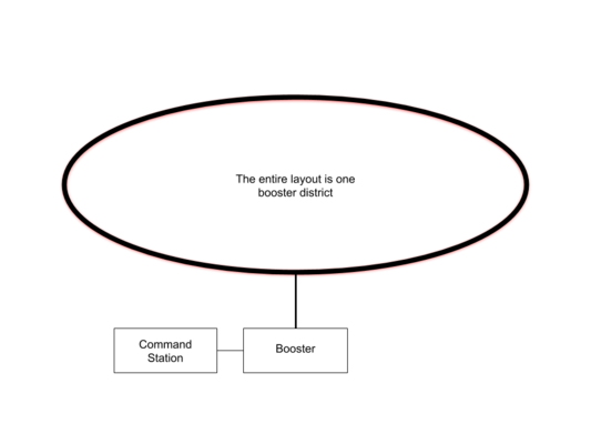
A Layout with One Booster Powering the Entire Layout
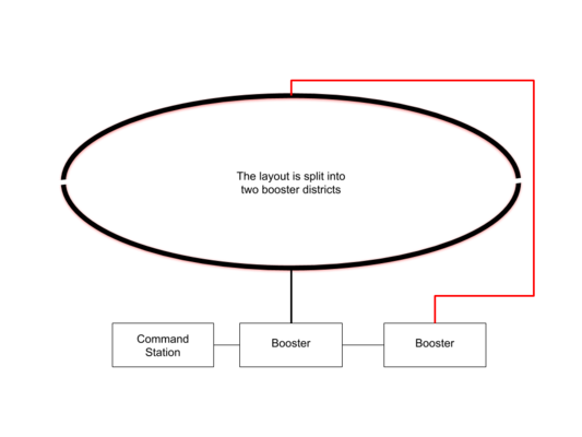
Layout with Two Booster Districts
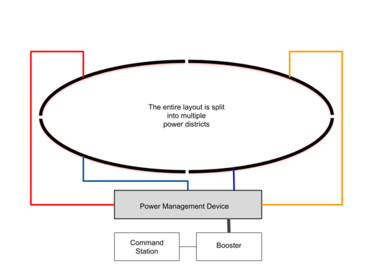
Layout with Four Power Districts


One might think having a single, large, booster/command station to power the entire layout is better. However, it's best to have a smaller booster districts powered by their own booster distributed around the layout. On a larger layout multiple boosters keep the power bus runs manageable. Using one high current booster for the entire layout could result in short circuits causing damage.
- Boosters should all have the same current (ampere) output. Combining a high current booster with a low current one, such as an 8A and a 5A booster, could result in destruction if an event connects the booster's outputs together. If possible, use a power management or circuit breaking device between each booster and the track.
Suggestion: Double gap the track to fully isolate the boosters. That is, both rails need to be cut at the same spot. Lack of gaps creates a short if one booster district goes out of sync with the others. Fill the gap with an insulating material, or use an insulted rail joiner, to prevent the gap closing up due to expansion and contraction of the benchwork.[5] Filling the gap also prevents the wheel from dropping into the gap and creating a short between two districts.
- If the train stops at a gap, the boosters may be out of phase. Disable auto-reversing (if equipped), as this can cause both boosters to enter an endless loop trying to match the other's constantly changing phase. Reversing the track power connections on one booster can correct that issue. You may need to make provisions to easily reverse the connections on a booster if it occasionally goes online out of phase with the other boosters.[6]
- To prevent boosters from going out of phase during power up, ensure the throttle network carrying command station signals to the boosters is active by powering up the command station, then the boosters. Otherwise, boosters can go online out of phase with other boosters and the command station's DCC signal.
Reasons for booster districts include:
- Additional trains,
- reverse sections,
- Isolating derailments.
Boosters are available with opto-isolated inputs, if that feature is required. The picture above shows one booster with a sticker stating "opto" on it.
Common Return: Be sure to wire a common return (sometimes called a ground) between boosters. This way they all have the same reference point. Power management devices may also require a common return to the command station or booster. This also functions as a low resistance return path when current needs to return to the source.[7]
Wiring
See the instruction manual for instructions on connecting the booster, and any additional boosters. It will also illustrate how to connect the input signals to the booster. Since the booster only requires a low-level data signal to operate, it is possible to incorporate boosters from other manufacturers into your DCC system.
For reliable operations, be sure to follow the recommendations on the wiring for digital control page when connecting your booster to the power bus.
See also
- Power Supply - Provides power to the boosters
- Command Station - Provides the commands boosters will use to send control signals.
- Power Management
- Power District
- Booster List
- Throttle Network
- Wiring for Digital Command Control
External Links
- DCC boosters for a model railroad - what to buy and how many
- Fleischmann/Roco Z21 Booster and Light Booster
- Booster Diagrams, NCE has instructions on adding additional boosters.
Booster FAQs
- Can One Command Station Control Multiple Layouts?
- Can Two Command Stations be used on One Layout?
- Can a Booster be used with a Digitrax Zephyr
- FAQ
- How much Track can my Booster or Command Station Power?
- NMRA Standards State Track Voltages Range from 7 to 20 volts. How are Speed and Direction Controlled?
- Phase Reversal, DB150
- Set Output Current, Lenz Power Station
- Should the DB150 be Blinking When Used as a Booster?
- What can burn out a decoder?
- What is a Headquarters
Other places that reference here
- CabControl
- Cab Bus
- DCC
- DCC Software
- DCC Tutorial - Starter Sets
- DCC in the garden
- DCS50
- DCS51
- Digital Command Control Advantages Over Direct Current
- Do It Yourself
- Fichtelbahn
- Mixed DCC and Analog Operation
- No Common Rail Wiring
- Power Bus
- Short Circuit
- Speed Steps
- Switching Speed
- Throttle Network
- Vhigh
- Zimo
- ↑ The term Power Station appears in NMRA DCC Standards.
- ↑ By building both the command station and booster into one package, substantial cost savings are possible.
- ↑ Before adding additional boosters verify the wiring is adequate. Upgrading wiring costs less than a booster.
- ↑ When adding additional boosters, it is important to split the track and power bus so that each booster feeds its own segment of track. Two boosters must never connect to the same track segment.
- ↑ While the metal rail does expand and contract with temperature, it is more likely that the wood used to construct the benchwork will experience greater dimensional changes due to humidity.
- ↑ Some early Digitrax boosters may randomly reverse their phasing if they are powered up before the command station begins sending data. In some instances, early boosters may have their outputs wired incorrectly internally.
- ↑ This "ground" is not the same as the earth ground provided by your house wiring. Never tie the low voltage side of your DCC system to house/earth ground.