NCE
Manufacturer: NCE
Summary: NCE began as an OEM in 1993, supplying hardware and software for the Wangrow SystemOne. NCE became a DCC manufacturer when Wangrow passed on the NCE Power House DCC system as the replacement for the SystemOne. Today NCE offers a variety of DCC Systems and accessories.
| See more Manufacturers | |
|---|---|

| |
| General information | |
| Phone | +1-585-265-0230 |
| Fax | +1-585-265-0234 |
| [email protected] | |
| CV8 ID# | |
| Main URL | Main URL |
| URL to manuals | |
| Address | NCE Corporation
82 East main Street Webster, NY 14580 |
| Date Opened | 1993 |
| Date Closed | |
| Successor | |
| Device Types | Booster, Command Station, Mobile Decoder, Other, Power Supply, Stationary Decoder, Throttle |
NCE Corporation
Company Summary
NCE DCC System
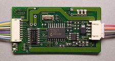
NCE Decoder
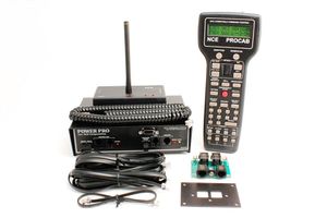
NCE Power Pro command station with 5A booster.


NCE began manufacturing DCC Products on an OEM basis in 1993 and was originally known as North Coast Engineering. They provided the software component of Wangrow's SystemOne and RamFixx Technologies' RamTraxx DCC systems. The name was changed to NCE when it was incorporated in 1996. Today, NCE has to grown into a full-time electronic design and manufacturing firm devoted entirely to the development and sale of products for the control of model railroads.
The NCE Power House was intended to be marketed by Wangrow as the next generation SystemOne. Wangrow declined, so NCE decided since it was a finished, ready for production product, they would release it under their own brand. Wangrow subsequently went out of business when their licence for the command station software supplied by NCE expired. Wangrow failed to comprehend the difficulty and time requirements needed to create their own software.
AML Interview with Jim Scorse of NCE
This is an audio podcast of an interview with Jim Scorse. Listen in the background if you wish. Youtube allows allows changing playback speed.
There are so many great folks to talk with in the AML Nation and one of the best, is our very own Jim Scorse the owner NCE. Jim has spent over twenty years building NCE into one of the most important companies in the hobby while he continues to innovate and improve his products year after year.
But like so many of our guests Jim isn’t just NCE, he’s passionate about model railroad operations along with his many outside interests such as trivia nights at the local pub, online racing, and his love of music. It’s a great interview and one we’re sure you’ll enjoy, so grab yourself a big bowl of shredded car cards, a steaming hot mug of melted solder and enjoy!!
Products
NCE produces a full line of Digital Command Control products
Starter Sets
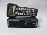
Power Pro Advanced Starter Set with external command station / booster. This set may also be equipped with the wireless option. (Radio version shown).
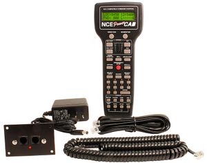
Entry Level Power Cab. Note the differences between it and the Power Pro system. The command station and booster are integrated into the throttle.
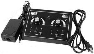
Basic starter set: NCE Twin


Advanced Systems
- Power Pro
- Power Pro R (Radio)
- Power Pro 10
- Power Pro 10 R
Originally this system was marketed under the Power House name. Complete system with Throttle (Pro Cab), integrated Command Station / Booster. A Power Supply is NOT included.
- Five- and 10-Amp versions available.
- Walkaround capability
- Expansion: 63 devices (Additional cabs and accessory items). NCE calls anything on the throttle network a "cab".
- Interface: Serial Port, RS232. USB adaptor card is not recommended as some commands are not available over USB connections.
- Programming Track connections, Programming Track Booster recommended.
The radio systems will be upgraded and increase the number of channels available in the process. It will be backwards compatible. [1][2]
Entry Level Systems
- Power Cab
While the Power Cab looks a lot like a Power Pro (they use the same package for the throttle), it is a 1.5A Booster, Command Station and Throttle integrated into a handheld device. If you disconnect it from the layout, everything stops as the DCC track signal is generated in the handheld. Adding a Smart Booster eliminates that issue. The tight level of integration limits the available current for the track power bus. Some software features are also absent.
The Power Cab features Pro Cab compatibility when connected to NCE Pro Cab / Power Pro command station it functions as a throttle. A cable to enable this feature is included.
The interface to the layout is called the PCP or Pro Cab Panel. It has connections for the ProCab, DC Power, and the Rail A and B terminals to connect the track power bus. It also has jacks to enable expansion of the system via the Cab Bus. Only three additional UTP panels are supported. In addition, three additional cab bus devices are supported for a total of three throttles and three accessories.
Supports USB interfaces for computer control
Basic System
- DCC Twin
This system features two throttles integrated into a single enclosure with the command station and a 3A booster. Limited programming options. Can also be used as a pair of throttles in another NCE system.
Power Pro compared to Power Cab
The Power Pro has additional features. While both units may look alike, there are some important differences:
- Computer interface: RS232, does not require a cab bus address to function, advanced features compared to other NCE systems
- Macro Capability Enhanced
- Accessory decoders last state is restored upon power up
- Control up to 250 locomotives
- Consisting: Up to 128 Advanced Consists possible, with additional consisting features.
Throttles
- Pro Cab/Pro Cab R
- ProCab Deluxe
- A Pro Cab is only a Cab/Throttle. Requires a command station and a booster
- Cab6
- Available singe throttle cab with radio and choice of rotary encoder or potentiometer. Four digit display. Can be used with YARD mode (center zero)
- Cab06r: Radio version
Discontinued
Wireless cabs
- Cab04pr
- Cab04r
Tethered Cabs
- Cab04
- Cab05
Notes
- A Pro Cab and a Power Cab look almost identical but they are two completely different products.
A Pro Cab is a Throttle only. It requires a DCC command station to function. It is a dumb terminal with a keypad and a display.
The Power Cab is a complete DCC system in one package. It is a Throttle, Command Station and Booster. All three in one (handheld) package.
- The Power Cab has a six-wire cable which connects it to the power supply, and also has wires which carry the digital DCC track signal and the throttle bus. This cable cannot be substituted with another. If you need a longer reach, the solution is to purchase a Cab06. They are available in tethered and wireless versions. The Power Cab must remain connected to the Power Cab Panel for the system to work.
- If you wish to run more than a few locomotives with your Power Cab, an SB5 booster may be required.
Each Cab must have its own unique cab address. Available cab addresses are based on the command station being used. Example: For a Power Cab system the available cab addresses are 3, 4, and 5. Addresses 8, 9, and 10 can be used for devices like the USB interface, AIU and Mini Panel.
Command Stations
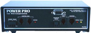
- PH-Box
- Power Pro System command station/booster
- CS02
- Command Station Only for Power Pro
- SB5 Smart Booster
- Five-amp command station / booster for Power Cab system, up to six throttles. NCE radio compatible. Converts to booster only if needed.
See this page for firmware revisions applicable to their command stations.
Boosters
NCE has used three product names in its manufacturing history.
- MASTER SERIES
- Power House
- Power Pro
- PB5
- Five Amp
- PB110A
- 10 Amp Booster with Automatic Reverse. Recommended for large scales.
- DB5
- Five Amp booster
Expansion Boosters
- DB3/DB3A
- Replaced by the DB5 Booster
- SB3/SB3A
- Replaced by SB5 Smart Booster
The SB5 and DB5 are 5A units. They are current production as of 2017
Smart Booster Firmware
Version 1.28
Version 1.65
- Total number of Cabs supported is 6, Addresses 2-7.
- Supports three AUI, USB or Minipanels on addresses 8-10
- Improved USB functions
1.65a
- Corrected issues with Dumb Booster modes
1.65b
- Number of cab addresses available after reset corrected
Older Units
- PB105. This model evolved into the DB and SB3 boosters. Available by special order only.
- PB110 10A booster, superseded by the PB110a
- PB205. Many PB205a boosters don't have the model's name marked on the front of the booster. Dual 5A boosters
Circuit Protection
- Main article: NCE/Circuit Protectors
Auto Reverser
AR10 10A Auto Reverser
Discontinued Products
| Name | Replacement | Status |
|---|---|---|
| CAB04P | CAB06P | |
| CAB04PR | CAB06PR | |
| CAB05R | DISCONTINUED | |
| CAB05 | ||
| SB3 | SB5 | |
| SB3A | ||
| DB3 | DB5 | |
| SWITCH-IT | SWITCH-IT II | |
| SWITCH-8 | SWITCH-8 MK II | |
| DIN PANEL | DISCONTINUED | |
| PACKET ANALYSER[3] |
See Also
- NCE FAQs
- NCE FAQ - NCE Frequently Asked Questions
- NCE Hints - Hints and tips for NCE products
- NCE Products - a more detailed list of NCE's offerings.
- Wangrow - Early DCC manufacturer which used NCE parts and software.
References to this Manufacturer
NCE FAQs
Q: NCE USB and Power Cab
Many users have issues with the NCE USB interface and the Power Cab. Particularly when attempting to connect with JMRI.
To begin diagnosing the issue, all the jumpers (1 – 4) must be in the OFF position on the USB interface.
For more details see: NCE Serial Communications and the Power Cab specific Power Cab and JMRI for details.
NCE USB Setup
Driver Installation
NCE has recently replaced the CP2102 USB Transceiver with the CH340 USB Transceiver. A different driver is required. If the Device Manager reports a CH340, do not install the SiLabs driver for the CP2102.
The process to install a driver for this device will be similar to that described below.
Microsoft Windows CP2012 Driver Installation
- NCE USB using the SiLabs CP2102 chipset.
- Download and install SiLabs CP210x drivers. '"`UNIQ--ref-000000E1-QINU`"'
The downloaded file will be a compressed Zip file.
- Open CP210xVCPInstaller_x86.exe for 32–bit computers or the CP210xVCPInstaller_x64.exe for a 64–bit computer
- The SiLabs device should appear as a new COM port in Windows Device Manager when the NCE USB device is plugged in
- A second install attempt may be required to get rid of the error symbol in Windows Device Manager
- If errors continue, removing driver in Device Manager and reinstalling may correct the issue
- The COM port should appear/disappear when installed correctly when connecting or disconnecting the NCE USB
- Do not attempt to set the baud rate in Windows Device Manager.
Configuration Instructions
The documentation contains some errors, so follow this procedure. It also explains how to read the version of your NCE USB:
- The first digit counts, the last three report how jumpers 2-4 are set
- Jumper 1 is ignored on all systems
- Always disconnect, then reconnect both cables on the NCE USB after making any jumper changes.
Power Cab
The correct settings for a Power Cab with V1.65 or V1.28 firmware and an NCE USB V6'"`UNIQ--ref-000000E2-QINU`"':
- All USB Jumpers 2, 3 & 4 in the Off position
- Jumper 1 is ignored
JMRI Preferences
- System manufacturer: NCE
- System connection: NCE USB
- Serial port: Appropriate selection for your computer
- USB version: V6.x.x
- System: PowerCab
- Additional Connection Settings checkbox ON
- Baud rate: 9600
The JMRI console log should report V6.3.0. If it reports V7.3.0 and your Power Cab is V1.65, use the settings below instead.
Power Cab V1.65 / V1.65b and an NCE USB V7
- All USB Jumpers 2, 3 & 4 ON
- Jumper 1 is ignored
JMRI Preferences
- System manufacturer: NCE
- System connection: NCE USB
- Serial port: Appropriate selection for your computer
- USB version: V7.x.x
- System: PowerCab
- Additional Connection Settings checkbox ON
- Baud rate: 19200
The JMRI console log should report V7.3.7
SB5 Instructions
USB Jumper 4 on. All others off
- At least jumpers 2 & 3 in the off position
- Jumper 1 is ignored
JMRI Preferences
- System manufacturer: NCE
- System connection: NCE USB
- Serial port: Appropriate selection for your computer
- USB version: V7.x.x
- System: SB5
- Additional Connection Settings checkbox ON
- Baud rate: 19200
The JMRI console log should report V7.3.1.
Troubleshooting
If the system does not work after this:
- If the SB5/Power Cab firmware version is V1.65 rather than V1.65B, there may be a firmware issue triggered by a System Reset.
- Your NCE USB may be set to an invalid cab address (V7 only).
- There is a potential hardware issue with the NCE USB/Power Cab combination.
In either case:
- Quit JMRI
- Ensure neither LED on the NCE USB is stuck ON
- If true, power cycle the USB by unplugging it from the Cab Bus cable
- Ensure you have no other throttles connected
- Restart JMRI and immediately go to Configure USB Interface under the NCE menu
- Set Cab ID to 3
- Attempt a JMRI operation
- Use a JMRI throttle, or attempt to identify a decoder
- The status line should stay green and it should work
If this is not successful, additional assistance is available on the JMRI Users Mailing List on Groups.IO. Be sure to cut and paste the console logs into any message requesting assistance.
Edit FAQ Related Articles: NCE Hints, NCE Power Cab, NCE PowerPro, NCE ProCab, NCE USB and Power Pro Command Station Related Manufacturer: NCE Categories: Command Station, Computer, Computer Interface
Q: Cab Bus Connectors
The NCE Cab Bus can use a DIN Plug, a TRS Phone plug, or an RJ–12 plug.
'"`UNIQ--gallery-000000E7-QINU`"'
DIN Plug
Using a 5 pin 180º DIN connector. From the left, with keyway at the bottom, going clockwise:
- +12 Volts (nominal)
- Ground
- "A" lead of RS-485 signal
- "B" lead of RS-485 signal
This is optional, can be used when wired for compatibility with the Lenz XpressNet
Three Pin (TRS) Phone Plug
- Tip: +12 Volts (7.5 to 16 Volts DC is OK)
- Ring: RS-485 "A" lead
- Sleeve: Ground
RJ-12
- Main article: Modular Connector
This connection is used for the Cab Bus. The UTP (Utility Throttle Panel) has these connections.
- Reserved
- +12 VDC
- A lead of RS-485 signal
- B lead of RS-485 signal
- Ground
- Reserved
Only the 4 inner wires are used. This is the preferred interface.
Cable Identification
- Cab Bus Cable with RJ12 connector 6P6C. A flat 6-wire cable is used for tethered cabs, UTP panels, the cab bus, and the Power Cab'"`UNIQ--ref-000000E8-QINU`""`UNIQ--ref-000000E9-QINU`"'. For regular cabs, the maximum length is 40 feet. The two outer wires (white and blue) on the six-wire cable provide the track power output of the Power Cab. In other applications the two outer wires are not used, including using it for the Cab Bus, RB02, and the direct connection between the RB02 and RPT1.
- Cab Bus Cable with RJ12 connector 6P4C. A 4-wire coiled cable 6 feet long is used for tethered cabs. Notice the 6-pin connector with only 4 slots being used. This is a regular coiled Cab cable. No track power. One length only,
- Control Bus Booster Data Cable with RJ-H connector 4P4C. A 4-wire cable is used between boosters and a command station. Maximum length is 300 feet.
- Clean Data is required on pins 3 and 4 for reliability.
It is very important to get the correct type of cable. Using a cable which flips connections will damage your equipment. Edit FAQ Related Articles: Cab Bus, What is the Cab Bus Related Manufacturer: NCE Categories: Throttle Network
Q: Programming the Option Key on an NCE Power Cab

The OPTION key on the Power Cab has a number of functions. The default value is 94, Brake. It can be changed for a number of different purposes.
See the Power Cab manual for full details.
A common use of the option key is to access extended functions, which requires changing the default value of 94 to 122, Extended Function Control. These videos demonstrate the process.
'"`UNIQ--item-0--QINU`"'
'"`UNIQ--item-1--QINU`"'
Edit FAQ Related Articles: NCE Power Cab, Accessing Functions above F9 with an NCE Cab Related Manufacturer: NCE
Categories: Throttle
See more FAQs!
- ↑ A Modeller's Life podcast, Episode 198
- ↑ Fall 2022
- ↑ Replaced by DCC Meter and Packet Analyser