Packet Analyser Operation
Summary: A packet analyser allows real time monitoring of the data stream on the power bus.
--- This page is under construction ---
DCC Meter / Packet Analyzer
This article demonstrates the operation and various output formats available from the NCE DCC Meter/Analyzer.
Operation
The device has several connections.
- Track Power In
- Track Power Out
- USB B port
Terminal blocks are supplied to allow easy insertion of the device. Wires are connected to the terminals, which are then mated with the correct connector on the device.
The meter is a flow through device, power is supplied by the track outputs on the booster, and the meter's output is connected to the track bus.
When track power is present it displays Volts and Amps.
A button toggles between the meter and analyzer modes.
Data Monitoring
To monitor data in the Analyser mode, a button below the display toggles between modes. When in this mode the display indicates it is now operating as the analyzer.
A terminal is connected via the USB port. A computer running a terminal program allows control and display of the data stream.
Modes and Commands
Note: There is an error in the printed manual regarding the Hexadecimal modes. The available modes are H0 and H1.
- H0: Only packet payload bytes are shown, with a space between each byte.
- H1: The Preamble and the number of bits are shown, followed by address and data bytes.
| NCE DCC Meter and Analyser | |
|---|---|
| NCE DCC METER | DCCWiki.com |
| Available Commands | |
| Display Modes | |
| Verbose | |
| V | Display packets in 'verbose' mode |
| Hexadecimal | |
| H0 | Hex display mode 0 |
| H1 | Hex display mode 1 |
| Options | |
| A+ | Display all accessory packets |
| A- | Don't display accessory packets |
| I+ | Display all idle packets |
| I- | Don't display idle packets |
| L+ | Display all loco packets |
| L- | Don't display loco packets |
| R+ | Display all reset packets |
| R- | Don't display reset packets |
| S+ | Display all signal packets |
| S- | Don't display signal packets |
| ? | Display list of commands supported |
| In normal operation space bar pauses/resumes display and LCD will display -- USB STOPPED -- | |
| Any packet that isn't decoded by the analyzer will be displayed in hex | |
| Reset packets will be displayed as: RESET | |
| Idle packets are displayed as: IDLE | |
Output
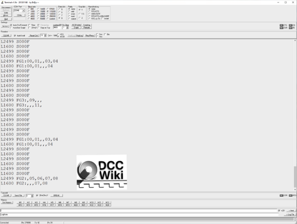
Verbose Mode
| NCE DCC Analyser | |||
|---|---|---|---|
| Verbose Mode | |||
| DCCWiki.com | |||
| Locomotive, Address | Speed and Direction | Function Group | Active |
| L2499 | S000F | ||
| L1600 | |||
| L2499 | FG1 | 00,01,,03,04 | |
| L1600 | FG1 | 00,01,,,04 | |
| L2499 | FG2 | ,05,06,07,08 | |
| L1600 | FG2 | ,,,07,08 | |
| L2499 | FG3 | ,09,,, | |
| L1600 | FG3 | ,,,11, | |
| L2499 | FG4 | ,,,,,,,, | |
| L1600 | FG4 | ,,,,,,,, | |
| L2499 | FG5 | ,,,,,,,, | |
| L1600 | FG5 | ,,,,,,,, | |
The speed is displayed as the number of steps (0 – 127) and the direction. If the multifunction decoder were operating in 14 or 28 step mode the display and values would change accordingly.
Functions are displayed as to which group they are part of, and their status. When not shown, the function is inactive.
Hexadecimal Modes
H0 Mode
| NCE Analyser | ||||
|---|---|---|---|---|
| H0 Mode (Hexadecimal Output) | ||||
| DCCWiki.com | ||||
| Address | Payload | |||
| C6 | 40 | A4 | 22 | |
| C9 | C3 | 3F | 80 | B5 |
| C6 | 40 | 3F | 80 | 39 |
| C9 | C3 | DE | 00 | D4 |
| C6 | 40 | DE | 00 | 58 |
| C9 | C3 | DF | 00 | D5 |
| C6 | 40 | DF | 00 | 59 |
| C9 | C3 | BF | B5 | |
| C6 | 40 | BC | 3A | |
H1 Extended Output
This mode prepends the Preamble, indicated by the letter P, and its value.
The example shows the preamble has 15 bits, one more than the nominal value of 14. This is useful for diagnosing issues such as data corruption or RailCom, as a multifunction decoder requires a minimum of 10 bits, and no more than 12 for proper operation.
| NCE Analyser | |||||
|---|---|---|---|---|---|
| H1 Mode (Hexadecimal, Extended) | |||||
| DCCWiki.com | |||||
| Preamble | Payload | ||||
| Extended Address | Data | ||||
| P0F | C9 | C3 | 9D | 97 | |
| 15 (decimal} | 195 | 201 | 157 | 151 | |
| 1111 (binary) | 1100 0011 | 1100 1001 | 1001 1101 | 1001 0111 | |
| P0F | C6 | 40 | 99 | 1F | |
| 15 | 197 | 197 | 197 | 197 | |
| P0F | C9 | C3 | 3F | 80 | B5 |
| P0F | C6 | 40 | 3F | 80 | 39 |
