Multifunction Decoder Installation
Summary: Installing a multifunction decoder for the first time can be a daunting task. After you've done a couple, it will be like second nature. This guide will help you through the process.
|
See the Video. |

Read the Instructions
Many decoder manufacturers provide much more detailed instructions on their website. Visit their site and download any manuals or other documentation they provide. Also read the instructions for DCC Conversion that came with the locomotive.
If this article is in conflict with the documentation provided with the decoder, follow the manufacturer's installation directions.
Process Outline
If the chosen locomotive runs poorly on analog power, installing a DCC Decoder will make no difference. Correct the drivetrain problems before conversion.
The following outlines the process of installing a DCC multifunction decoder.
- Determine the locomotive's stall current
- With modern (made in the last 20 years) this step can be considered optional, as they have much improved motors and drivetrains.
- Determine where the decoder will fit in the locomotive/rolling stock
- Select a multifunction decoder
- Determine if there is a socket for decoder and select a matching multifunction decoder
- Select a multifunction decoder that fits inside the body shell
- Has the required current rating
- Isolate the motor from the track pickups
- Check that the couplers are isolated from the frame. In some cases, metal couplers can create a Short Circuit between two locomotives.
- Verify the motor is isolated from the frame
- Install the decoder along with wiring for any extra effects
- Test the completed installation.
- If you have a locomotive designed to meet EU requirements, please read this on their RFI Suppression Circuit. If the locomotive will stay in the EU, it must comply with the regulations, which will require a decoder designed for service in the EU.
Measuring the Stall Current

This procedure is Optional for modern locomotives. Those manufactured in recent years have much more efficient motors and drive trains, which draw less current than older models. If the conversion involves an older product manufactured prior to the turn of the century, checking stall current is necessary.
- You will need a meter (a multimeter or an ammeter) that can measure DC current.
- Connect the DC ammeter in series with your analog power supply and the track (see picture on right). The ammeter is wired in series to measure all the current flowing in the circuit. Be sure to use the terminals marked "Track" or consult the instructions for the power pack if you are not sure. Do not use the "Accessory" terminals as they are alternating current.
- Set the meter on the DC Amps (DCA) scale, and set the range if needed. If the meter isn't autoranging, use a high range first to determine the range needed. It may also require connecting a lead to a specific terminal. Be aware that some ammeters may not have a fuse in the circuit for certain ranges.
- Grasp the locomotive so it doesn't take off and turn the power pack to full.
- Push down until the motor stalls (stops) and note the current. This is the stall current. Do not allow the motor to stall for more than 5 to 10 seconds. Doing so can cause damage to the motor, or other electrical components of your locomotive.
Plan the Installation
Determine Where the Multifunction Decoder Will Fit
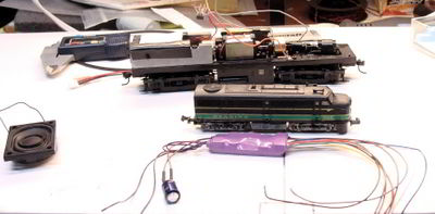
Sound decoder, N Scale locomotive, and frame of a similar locomotive in HO.
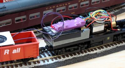
Decoder mounted on weight
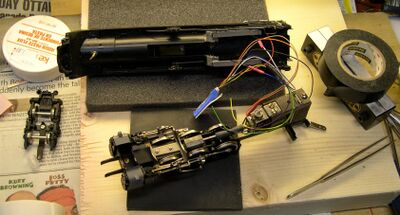
Decoder being installed in a boiler
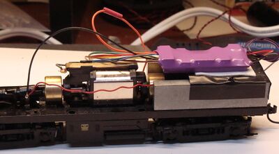
TSU installed in an FB-2
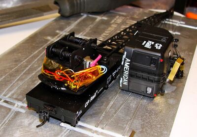
NCE N Scale Decoder installed in a Walthers American Crane


Decoder siting is often the most difficult problem to solve during the decoder installation. The decoder needs to be located in a place meeting several criteria:
- There must be room for a decoder
- Is it away from heat sources, such as incandescent lamps or the motor?
- It should ideally have free air around it for cooling
- Without proper cooling, the decoder could overheat and be damaged. Some decoders have thermal protection to prevent this - it will simply shutdown.
- It should ideally be invisible from outside
Finding room for a decoder is unsurprisingly easier on larger models, and becomes more and more difficult as the scale (or size) decreases.
Ideally, the decoder should be located in the same area of the loco as the motor and pickups. It is possible to place the decoders in the tender of steam locomotives if needed. Some people have been successfull at installing decoders in rolling stock and permanently coupling it to the loco. However, this should be a last resort as you will want to change rolling stock in the future.
If a sufficiently large area cannot be located inside the locomotive, it may be possible to create space by removing some of the material from the body or chassis. If the installation appears marginal, try assembling the model with plasticine or blu-tack in the space being considered to find out how big it is with all the parts in place.
"N" and "Z" gauge models are considerably more difficult than say "G", but there are some small decoders available now. However, it is likely that material will need to be removed, though. See below for specific scale information.
Sound Decoders
Select the largest speaker which will fit. If that isn't possible, two or more smaller speakers will perform the same. Larger speakers have better low frequency response, and can produce louder volume, for a better sounding locomotive. Many installs are now using speakers designed for the iPhone, which are efficient and provide good sonic performance.
A proper enclosure/baffle is needed to optimize the sound quality. A poor baffle, or none at all, results in poor or weak sound. Read the page on speakers for more information.
Enclosure Volume
The enclosure should fit the speaker. Too small and the sound will be muffled, and frequency response suffers as well.
The ideal size is one based on the size of the speaker. There should be a cubic relation between the dimensions of the speaker and its enclosure. For example, a speaker measuring 1" should have a 1 cubic inch enclosure, or 1 × 1 × 1" in dimension.
The enclosure should be stiff to reduce or eliminate resonances, and securely affixed to prevent distracting vibrations.
Motive Power Considerations for Sound Installs
Steam
Steam provides a tender, which can solve several problems: Decoder location, airtight enclosure, and easy locating of the speaker.
For the best sound, the speaker cone should face out in free air. This can be done either through the coal load, or the floor of the tender. A baffle can be constructed if needed. The coal could be perforated with small holes to allow the sound to escape, or a hole can be cut into the floor.
Diesel Electrics
The decoder will be, by necessity, installed in the car body. Avoid locating it on top the motor, for temperature considerations. Locate it where possible in an area where airflow can help cool the decoder. Speakers are often installed in the fuel tank, or under the roof top fans. Again, a baffle is required for optimum sound quality.
Select a Decoder
Once the stall current has been measured and the available space has been found, you can move onto selecting a decoder. There is a lot of information available on various decoder sizes and specifications. You can see a local comparison list of decoders, however since it's brand new, it's not anywhere near complete. You can also find information on various manufacturers' websites, as well as other DCC related websites.
Many decoders are made to go into a specific locomotive for a particular scale. Please see the scale specific article below.
However, it is possible (and in fact many model railroaders follow this practice) to use an N scale or even a Z scale decoder in an HO gauge locomotive. As long as the current rating of the decoder meets the minimum requirements of the locomotive (most newer HO locomotives have a rating of 1 amp, as do most decoders currently in production) then there shouldn't be any difficulties using a smaller scale decoder. Because larger scales (O, S & G) have a higher current rating only decoders made for these scales should be used.
The decoder mandatory requirements are that it must have an adequate current rating (i.e. can supply the stall current continuously) and that it will be small enough. There are however other considerations to take into account:
- Are any "accessory" outputs required? Most decoders can control one or more accessories - e.g., lights, windscreen wipers, uncouplers, sounds.
- How many speed steps are needed?
DCC Ready
A number of locomotives offered for sale are advertised as DCC Ready. This term can mean several things.
- Being DCC Ready could mean that the motor is already isolated from the frame, meaning you will not have to isolate it prior to installing a decoder.
- It can also mean that the locomotive is equipped with a decoder interface allowing a suitable decoder to be connected using a compatible plug.
- Some locomotives may have a light board with connection points for a decoder, cutting a couple of traces will disconnect the motor and lighting from the track pickups. The PCB can be left in and used as a connection point, or removed. The internal wiring is usually not soldered to the board, making removal easy.
Isolating the Motor

The motor must be completely isolated from all track pickup points. If the locomotive has a built-in command control socket, (usually advertised as DCC Ready) the motor is already isolated and should be DCC ready at this point.
Checking Motor Isolation
An older model or one without a NMRA socket requires finding and eliminating all connections between the motor brushes and track pickups. Typically, this is the biggest problem people have when they first get into DCC. Diesel locomotives are fairly straightforward, but with brass steam engines the mechanical pickups can be quite ingenious and well hidden - and may take some time and work to get these units DCC ready. Some models will have a circuit board that routes power to the motor and the lights. You may need to cut a couple of traces to disconnect the motor from the power source. Check the instructions that came with the locomotive.
Verifying the wiring, and the motor isolation checks require an ohmmeter. A simple analog or digital MultiMeter will suffice. Set your meter on the Ohms (resistance) scale and touch both probes together. The meter will indicate a short (0 ohms), and will test your meter (and its battery) for proper operation.[2]
The first test should be to determine that the wiring is correct and functional. Touch one probe to a motor terminal, follow the wire, and the other probe to the truck or wheels it connects to. Check both trucks if the locomotive has "all wheel" pickup. Do the same for the other motor terminal. Correct any wiring problems, such as bad connections or cold solder joints, then proceed to disconnect the motor leads from the power source, as per the decoder and locomotive maker's instructions.
To verify electrical isolation, you will need an ohmmeter. Place one of the probes on a brush or power terminal on the motor, then touch the other probe to the chassis or right rail pickup wire, then move to the left rail pickup wire. If the motor is isolated you will read an open circuit on the ohmmeter. Move the probe to the other brush and repeat. If both tests indicate an open circuit, the motor is isolated and you can safely proceed with decoder installation.
Installing the Decoder
Before installing a decoder, especially if you haven't done this before, please read the pages on Soldering and ESD Protection. It is vital to have the correct type of solder, the appropriate flux, and a soldering iron/station suited to working with electronic devices.
Connecting the Motor
How the motor is wired is defined by the NMRA. See the page on Locomotive Interfaces for more information.[3]
Make note of the wire which connects to the pickups on the right side of the locomotive (where the engineer sits). The motor terminal it connects to is the POSITIVE (+) terminal, which is connected to the ORANGE wire from the decoder.
Lighting
Lighting can be done using incandescent lamps, or LEDs. Many decoders have track voltage outputs for their lighting, so appropriate wiring is required.
Tips for Incandescent Lamps
When using 12 – 16V bulbs, nothing additional is needed. However, incandescent bulbs have a surge current when cold, up to 10 times their rated amperage. For example, a 40ma bulb can have up to a 400ma surge current when turned on cold. This probably won't kill the decoder on the first turn-on, or even the second, third, or three hundredth, but it will wear on it, and could damage it in the long run. To limit the current, add a 47Ω resistor in series. This isn't enough resistance to dim the lamp much, it will limit the surge and help protect the decoder. If you can add more than 47 ohms without dimming the bulb below your requirements, so much the better.
LEDs
If using Light Emitting Diodes, every LED shall have a series resistor to limit the current. The series resistor can be installed on the anode or cathode side.[4]
Testing the Decoder
Decoder Testers are available which allow you to test the decoder prior to installation, and even configure it first.
Use a program track the first time to test the installation. The program track limits the current, so an incorrectly decoder will not be destroyed by a short circuit.
After Installation
- After installing a multifunction (or function) decoder, leave the vehicle's shell off until the install has been verified as correct. Ensure the decoder(s) are insulated from the chassis.
- Put the chassis with its decoder on the programming track
- Attempt to set the desired address
- If an error results, stop! There may be a short, which must be corrected first.
- Some DCC systems impose limits on available addresses. This limitation may apply to the decoder too.
- If the address change is accepted, continue configuring the decoder.
- Testing the installation on the main line at this point will confirm that lighting effects and direction of travel is correct. Make necessary corrections.
- If the results are satisfactory, the shell can be installed on the chassis and any further tests conducted.
- Return the vehicle to the programming track and continue with any additional configuration of the decoder.
Troubleshooting
One feature that can cause problems is RailCom being active. Some decoders are not compatible with RailCom.[5] Turning RailCom off in your command station usually solves the issue. If you wish to use RailCom on your layout, select decoders which are compatible with RailCom.
Troubleshooting an Eight Pin Connection
If the locomotive will not work after installing a decoder with an 8-pin connection[6], see this page.
Vehicle Runs in Reverse
If the vehicle runs in reverse, the motor connections are backwards. Swapping them will solve the issue.
This may not be possible with a "drop in" multifunction decoder.[7] In a stiuation like this, using the NDOT flag in CV29 will be necessary, providing the headlight operation can be reconfigured for proper operation.[8]
Further Reading
- Decoders
- Multifunction Decoder Install List - List of decoder installation documents.
- Hardwired Decoder - Wire colour codes and functions.
- NMRA DCC Plug - Standard pin assignments.
Videos
There are a number of related videos available to watch:
- Decoder Do's & Don'ts with SoundTraxx
- Soldering Tips from SoundTraxx
- Soldering for Beginners with SoundTraxx
- Soldering Flux
- Decoder Reset
- Modifying an Atlas N scale GP39-2
- See the Curated Videos page for even more!
External Links
- TCS has instructions on how to strip and tin a wire for decoder installations: TCS Wire Guide
Identify Electrical Connectors
European Websites
- These sites are not in English. They may offer a page in English or require translation.
Installing decoders in European Outline Locomotives
- Decoder installations of all formats and sizes
- Installation and Programming of NMRA-DCC-Decoders
- Selection of NMRA DCC Compliant Loco Decoders
Videos
Different Types of Motors & How to use them with a Decoder
Eight, Nine & 21-pin Installs Made Easy
- ↑ The 14 speed step mode is obsolete, 28 speed steps are the default now.
- ↑ If needed, the zero point may be adjusted on an analog meter which has a "Zero Adjust" knob.
- ↑ Reference: NMRA Electrical Standard S-9
- ↑ Multifunction decoders follow the 'common cathode' convention, meaning the blue wire is the Positive connection for the LED.
- ↑ Some early multifunction decoders do not work well with the reduced number of preamble bits present when the RailCom cut out is active.
- ↑ Sometimes called an NMRA plug
- ↑ There have been numerous reports of Atlas locomotives which were wired incorrectly at the factory, resulting in the locomotive running in reverse after a drop in decoder has been installed. (2022)
- ↑ NDOT controls not only the motor direction, but the operation of the headlights for prototypical operation. When used to correct a wiring issue, it means the headlight will be on while the locomotive is moving in the reverse direction, and the correct light will be off.