DCC Bus Signals
Description
NMRA standard S-9.1 described the DCC signal as:
"The NMRA baseline digital command control signal consists of a stream of transitions between two equal voltage levels that have opposite polarity."
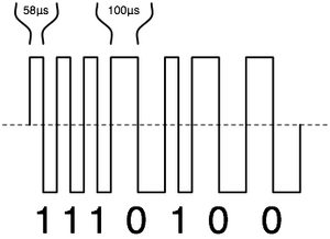
The waveform at right illustrates what the DCC track voltage would look like when viewed with an oscilloscope when measure with one probe on one rail and the probe-ground on the other rail. The dashed center-line represents 0V. The track voltage alternates between a positive and negative voltage
Each data bit is represented by two polarity reversals occurring after the same amount of time. The wider, 100 usec width pulse represents a data 0 and the narrower, 58 usec width pulse a data 1. In this diagram, the positive pulse comes first. If the probes to each rail were reversed, the negative pulse would come first.
Extracting a DCC Signal
The DCC decoder uses a bridge rectifier to convert the track voltage to DC to power the processor, motor and LEDs.
A higher speed opto-coupler 6N137, connected across the rails just like the rectifier is used to convert the alternating pulses on the track to a uni-polar logic level connected to a digital input of the processor. The processor measures the time between polarity changes. It could recognize a data zero when the time is greater that 80 usec and a data one when less than 80 use. Regardless of polarity of the track connections to the decoder, the opto-coupler will see two polarity changes for each data bit.
Figure-1 in NMRA Standard S-9.2 show a basic DCC packet composed of a 12-bit preamble, address, instruction and error detection bytes. Since each byte is separated by a zero bit, it is relatively easy to recognize the preamble and the start of a DCC packet. (also see DCC Packet).
Generating a DCC Signal
The command station generates a digital signal at conventional logic level voltages 0 - ~5V, which is an input to one or more boosters. The boosters translate the the 0-5V signal to a track voltage -15-15V using an H-bridge.
An H-bridge is commonly used to control a DC motor. Only two of the four transistors are turned on at a time, determining the polarity of the output voltage and typically the direction of the motor. A PWM signal determines the duration that the transistors are turned, determining the speed of the motor. 40% of the time results in an average of 40% of the supply voltage.
An H-bridge is idea for generating the alternating polarity of a DCC signal. The command station signal determines the polarity, as if constantly reversing the direction of a motor with a PWM that is constantly on.
| Logic
Level |
Polarity | Rail-a | Rail-b | Vab |
|---|---|---|---|---|
| 0 | - | 0V | 15V | -15V |
| 1 | + | 15V | 0V | 15V |
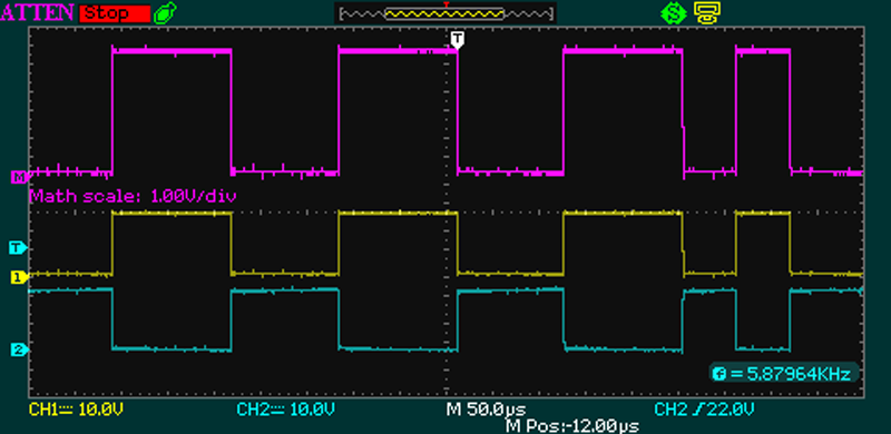
This is illustrated in the oscilloscope trace. The yellow and cyan traces are measured with a probe on each rail and the probe-ground connected to the DC ground of the booster. The yellow "1" and cyan "2" on the left side indicates the ground reference of each trace, where the probe voltage is equal to the probe-ground. Both traces alternate between 0 and 15V and are opposite one another.
The top magenta trace is generated by the oscilloscope by mathematically summing the two other traces. It is from 0-30V, but does not indicate a ground reference which would be at the mid point.
Signals on the DCC Power Bus
Oscilloscopes display signals as vectors, as they have both amplitude and direction. While the probes connect to the Rail outputs.[1]
The Purple trace is twice the amplitude, which is the sum of Channels 1 & 2. The purple trace represents a Differential Signal with no Ground[2], as per the NMRA Standards.[3][4][5][6]
The digital data is represented by the time (period) the rail is energized. There are no positive and negative voltages on the rails, the rail is either On or Off. The multifunction decoder only sees its input signal go high (On) and low (Off). A total period of 58µS High + 58µs Low (116µS in total) represents a binary value of 1, a total period of 200µs represents a 0 value.[7]
This is not an AC[8] signal, as the rail will have a voltage or no voltage present at any point in time. What is happening is the current is changing direction as it moves from one rail to another. Measuring this with an oscilloscope will display a peak-to-peak signal, which many will claim supports their assertion that the signal is an AC waveform. Since this measurement is made with the track outputs floating, the trace indicates which connection was more positive than the other at a point in time. [9]
This method of transmitting data and power in the same signal results in a very robust signalling technique with a high signal to noise ratio, while reducing space charges around the rails and the electrostatic attraction of contaminants. A multifunction decoder can receive data regardless of the orientation of the vehicle, as either rail has the On/Off signal available.
c
- ↑ Since the booster output is floating, there is no need for use of a "differential probe" as is often claimed.
- ↑ The term Ground is incorrect, as ground should only refer to the point where the electrical system is connected to earth ground. The correct definition is floating, as there is no fixed reference to a point on the booster.
- ↑ Read the entire document and any notes. The standard is deliberately not specific, as it only describes what the result should look like, not the exact construction. Also note it does not define polarity, as that is a quality wherein the direction the locomotive defines the "positive" rail.
- ↑ Differential Signal: One signal is in the High State while the other is Low, allowing Common Mode Rejection of any noise which may be present.</><ref>Read the entire document and any notes. The standard is deliberately not specific, as it only describes what the result should look like, not the exact construction. Also note it does not define polarity, as that is a quality wherein the direction the locomotive defines the "positive" rail.
- ↑ Differential Signal: One signal is in the High State while the other is Low, allowing Common Mode Rejection of any noise which may be present.
- ↑ The correct terminology in the NMRA Standard should be "floating". The track voltage is “floating”, meaning it has no reference to a common point. The measurement is taken as the voltage difference between the two wires. As the measurement is floating, this gives rise to the myth that the DCC signal has both positive and negative components.
- ↑ The data is represented by the time between the leading edges of the pulses.
- ↑ Alternating current is continuously changing in amplitude and direction in time, where the current follows the voltage.
- ↑ The output of the booster is floating, as there is no fixed reference point such as a chassis ground for zero volts. In this case, the "ground" clip is connected to one of the rails, making this trace possible.

