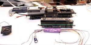
Proto 2000 with Tsunami
Summary: Installing a Tsunami Diesel Digital Sound Decoder in a Proto 2000 FB-1.
| See more Decoder Installs | |
|---|---|

| |
| General information | |
| Original Author | User:Terminator |
| Scale | HO |
| Est. Install Time | |
| Date Installed | 2009 |
| Decoder Product | TSU-1000 |
| Installed Into Product | Proto 2000 FB-1 |
| Keywords | |
Overview
Note: Read all documentation that comes with the locomotive and the decoder. The papers with the decoder are very simple, detailed manuals are available on the Soundtraxx Web Site. They will be of assistance during wiring and programming.
This unit comes with a rather complex looking light board. Yours may appear different, but it does the same thing: Controls the lights. It is not a DCC decoder despite appearances.
Basic Information
The locomotive in question is an ALCO FB-1, so the decoder was chosen for the ALCO 244 engine used in this model.
This is a "B" unit. Which gives more leeway as there are no lights or a cab. The prototypes were erected in 1949-1950, and were in service until the 1970s. Some were also converted to "robots", meaning the engine and generator was removed and replaced with radio control equipment, which then was used to control locomotives consisted to it in mid-train helper service
The electronic equipment underwent rapid reductions in size, to where the radio systems could be installed in the nose of an SD-40. At this point the robot cars were scrapped.
The reason for installing a sound decoder in a B unit is to enhance the realism when operating as a A-B set, or with other locomotives which may not be ALCOs. The unit was originally converted to a DSX-LL series sound decoder, but the poor sound performance due to noisy motor operation resulted in this conversion. The DSX decoders will be re-tasked to service for sound/function only in dummies.
Getting Started
If the shell is installed it must be removed first.
The logic board at the back of the frame, located on the weight, is not needed and will be removed. After removal, remove the screws that hold the weight in place and remove it completely. The weight will indicate the rear of the locomotive in this tutorial.
Make note of the wiring used in the unit. In this case, the frame is connected to one side of the trucks, and two feeders come off the left side of the trucks to complete the circuit.
Unsolder the wires from the trucks. For ease of installation, solder a length of wire connecting each truck. Don't solder the front truck connection until later. Replace the weight.
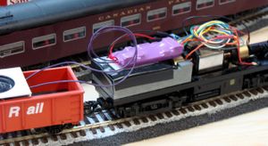
Build a platform on top the the weight to support the decoder. In this install double sided tape was used to hold the decoder in place.
Installing the Decoder
Place the decoder on top of the weight. Position it so as to not pinch any wires when the shell is re-installed. It may be easier to place it so the wiring harness for all the connections faces the front, with the speaker leads and capacitor coming out toward the rear.
Once an ideal position is found, fix the decoder in place. Once secured, wiring can commence.
Tie down the wires as needed so they don't interfere with other things.
Wiring
Title=Chassis
Since this is a B unit, lighting is optional. So wiring is very simple.
Cut, strip and connect the black wire to the terminal on the front truck, and along with the wire from the rear truck, solder in place.
The "right side" wire is the red one, which is attached to the frame. Remove the screw holding the lug in place, and unsolder the wire. Cut the red wire to length, strip and solder to the lug. Reinstall the lug.
Motor
The motor has two wires. The grey wire is connected to a metal strip on the top of the motor. Carefully remove this strip. Carefully, because there is a spring beneath it which presses against the brush, and carries power to the brush in the process. It should pop off easily.
Unsolder the wire from the metal strip. Use solder wick to remove the solder and open up the hole the wire passes through. Cut and strip the Grey wire from the decoder, thread it through the hole and solder. The other wire coming up from underneath the motor needs to be cut and stripped. Push a small length of heat shrink over the wire.
Then cut and strip the ORANGE decoder lead, twist the two wires together and solder. Fold the soldered section parallel to the wire and slide the heat shrink over it.
At this point, the installation is basically complete. Use some heat shrink to gather the extra wires together to ease of handling later.
Lighting
This is a B unit so it doesn't have the lighting an A unit would have. It could have interior lighting, using the decoder's light outputs. A LED or two would suffice. You may want to use a function output driving a red LED to simulate fire in the mufflers... A function which is available.
Sound
For this install, a Soundtraxx one inch speaker was used.
The speaker is connected to the purple wires. Soundtraxx rates the decoder as one watt into eight ohms.
Mounting
Mounting the components.
The Baffle
For better performance, a baffle made by Soundtraxx specifically for the P2K FA/PA will be employed. Some assembly is required. The baffle is designed for a one inch round speaker.
Baffle Assembly
The baffle was assembled using contact cement. Simply apply some contact cement to both surfaces, allow it to dry as per the instructions, and assemble the baffle.
Before using contact cement, make sure it is compatible with the materials you wish to bond. Contact cement has a nasty habit of dissolving plastic materials!
Completed Baffle
After assembly, the baffle is quite strong.
Test fit the speaker and the baffle. The speaker will be mounted on the inside of the baffle. See the picture for how it will mount. This will demonstrate where the contact cement will go for the final assembly.
Apply (carefully!) a small amount of contact cement on the speaker's gasket (the gasket will fit against the baffle), and apply some to the inside of the baffle as well. When ready, bond the speaker to the baffle. Since the cement is dry and tacky, it will not seep into the speaker when mounting it on the baffle. As shown in the picture, there is contact cement applied around the perimeter of the hole in the baffle. The speaker gasket will be bonded to that.
Before doing so, align the speaker terminals the way you want them, to make wiring easier. Do not solder the wires on yet!
Once the speaker is bonded, you can prepare the decoder's purple wires for soldering. Strip and push them through the holes punched in the baffle's side.
Use a drop of flux or some paste flux on the wire, and position it on top of one of the solder pads found on the rear of the speaker. With a hot iron, quickly solder the wire to the terminal. Repeat for the second connection.
Polarity is not important in a one speaker setup. The wires are both purple, so polarity is unknown anyway.
Check your work
Before energizing the decoder, check and verify your wiring.
If you have a program track, it may be a good idea to verify the install on that. Most program track boosters include protection circuits in case of a badly wired install.
If all is good, it is time for a quick run on the mainline. If you hear no sound, make sure the MUTE function has not be engaged for that address. The Tsunami, like many other decoders, will have the default address of 03.
If everything works as it should, the next step is to program the decoder.
Testing
First run on the test track, then on the main track.
Test Track
If you have checked your wiring, check it again, then we are ready for the test track. The best option is to use a programming track with a booster, as this can detect a problem before it becomes a big problem.
Since this is a B unit, without a cab, it really has no "forward" direction. For argument's sake, the rear end will be considered as the one with the weight.
The shell of this model actually has an "F" to indicate the front.
Main Track
If the unit checks out ok, you can run it on the main line. Without the body installed you can see the pilot and error lamps. The error lamp lights with the headlight. For any questions, refer to the appropriate Soundtraxx manuals. The pilot lamp is on the side, and indicates power is available. The error lamp is at the back of the PCB, and will flash if an error occurs.
On the mainline the "engine" should start up. If no sound is heard, check the mute function with F8. The engine should respond to the throttle and move according, with the prime mover notching up. F2 and F3 operate the horn, F1 the bell, F4 is the dynamic brake, F9 and 10 control the RPMs, F11 the brake squeal/release, and F12 is the coupler clank.
The Tsumami Diesel Decoder is as bad as the steam version when it comes to options and configuration. Read the manuals and for maximum enjoyment, use DecoderPro to set up your new loco.
Closing It Up
Carefully place the shell onto the chassis, being careful that wires don't get pinched in the process. Watch clearances around the speaker too, so that wires don't impede operation or distort the sound.
Once everything is in place, insert the screws and gently tighten them. Do not over tighten them.
Related FAQs
- No FAQs link to this page.
See Also
- Tsunami TSU-1000 - More detailed information on DCCWiki.
- FA-2 Installation
- TSU Diesel Reference (PDF File)


