PECO Electrofrog
Summary: The PECO Electrofrog is problematic for Digital Command Control, by nature of its Power Routing capability. Simple changes will make it work flawlessly with DCC.
|
See the Video. |
PECO Turnouts

Peco offers several types of turnouts:
- The Electrofrog, subject of this article
- Insulfrog
- Unifrog, a new product which is intended to replace the Insulfrog and Electrofrog products. These products will be gradually phased out and replaced by the Unifrog line. [1]
Differences between PECO's Electrofrog and Insulfrog Turnouts
The electrical power routing of the Peco Electrofrog is different than that of the PECO Insulfrog.
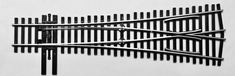
Electrofrog turnout by PECO
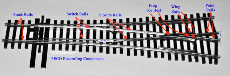
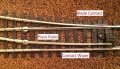
Parts of a turnout


The Electrofrog is a well-designed turnout. There is no plastic for wheels to run on. The positive locking action of the switch points makes it the ideal turnout for anyone's layout.
The main feature the metal wing rails, resulting in an all-metal frog. The Insulfrog may have an all plastic (non-conducting) frog, or a metal one with gaps. With DCC operation, there are a couple of problems. The solutions, however, are simple.
Be aware that images often used to illustrate PECO's turnouts may be incorrect. In many advertisements the pictures are of Electrofrog turnouts, despite the ad copy saying differently.
Differences between Electro and Insulfrog Turnouts
There are a number of mechanical, electrical and physical differences between the two models.
Insulfrog
- Frog may be cast entirely in plastic;
- Closure and wing rails are solid;
- Plastic filled gap where closure rails meet at the toe of the frog;
- Beginning of frog itself is plastic;
- Wing rails may also be cast in plastic;
- Switch rails are electrically isolated;
- Power Routing: Closure rails are electrically connected to the appropriate Point Rails.
Electrofrog
- Closure rails are not gapped before the frog;
- While there may be a physical gap, the closure rail is electrically connected to the frog's wing rail
- Jumper wires underneath connect the frog to the closure rails;
- Frog, wing, point, closure rails and switch assembly are electrically a unit;
- Closure rails are electrically connected as a pair;
- The point rails which form the frog are powered by the switch rails;
- This creates the power routing capability of the Electrofrog.
Power Routing In An Unmodified PECO Electrofrog
PECO's Electrofrog switch was designed in the days of analog operation with the ability to power sidings depending on which way the switch rails were aligned. Drive a locomotive into the siding, then set the turnout for the mainline route. We could rest assured that the locomotive wouldn't creep away on us – assuming there were no additional track power feeds to the siding. The turnout would function as an electrical switch in addition to its duty as a track switch.

Basic Rule of Electricity: Current will only flow if there is a difference in potential between two points.
We could then flick the switch rails on another turnout which held another locomotive on that siding, then operate that new locomotive. This ability had everything to do with how the Electrofrog was wired: By a combination of the rails and wire bonds on the underside, the switch rails acted as an electrical switch that routed power to either the mainline or diverging route via the point rails.
- With the Electrofrog aligned for the main route, Rails A1 and B1 have a voltage potential between them. The point rails are powered by the switch rail alignment, and are both at the same potential. There is no potential difference between the siding's rails past the frog, so the siding is electrically dead.
- Realigning the switch for the siding changes the connection to the frog. There is now a potential difference, energizing the siding.
- With DCC, the point rails will short the DCC Power Bus via the switch rail.
While it was not obvious, if the switch was set for the mainline route, a whole lot more than just the mainline route was electrified. Look at the red rails in the photo above. Hard to believe that all of these rails, particularly the switch and both point rails are also powered when the switch is set for the mainline route!
Electrical Behaviour of an Unmodified Electrofrog
Ohming out an Electrofrog reveals a few basic truths: (Refer the photo above)
- The Stock Rails are not electrically connected to anything.
- The Switch, Closure, Wing and Point Rails are electrically one unit.
- The Frog (formed by the Wing and Point rails) is electrically bonded to the Closure rails.
- The Point rails are electrically bonded to the Wing rails at the heel of the frog
- The physical position of the Switch Rails against the Stock Rails determines which phase is connected to the frog
- The switch rails form a SPDT switch
- This creates the power routing capability of the Electrofrog design
- The point rails create a short, as they are not independent.
- There is length of wire connected at the heel of the frog for external power
Digital Command Control eliminated the requirement for power-routing switches. Locomotives only moved when told to move (via the throttle). When parked, they stayed parked, even though there was still power on all the rails. We also added all kinds of track feeds because we didn't have to worry about power-routing to sidings, particularly around turnouts.
Good DCC wiring practice requires track feeds before and after a turnout. Which caused problems with the Peco Electrofrogs. Because the switch routed the power, depending on how things were wired, Electrofrogs shorted the DCC power bus.
Shorting In the Electrofrog
There are two places where a short occurs.
- The Point Rails: Without isolating them from the track, the point rails will connect Rail A to Rail B, immediately creating a short circuit. Using insulated rail joiners eliminates that possibility.
- Shorting between the Switch and Stock Rails. An out of gauge metal wheelset can create a bridge between the switch rail and the adjacent stock rail, as both switch rails share the same phase. This means a wheel can bridge the gap between the adjacent and out of phase stock rail if the back of the wheel grazes the switch rail.
Making the Electrofrog DCC Friendly
These modifications are recommended by PECO, and illustrated in their data sheet. See the links at the end of this page for links to various PECO documents. The Electrofrog does not require modification for use with Digital Command Control as found in the package. The modifications listed help improve reliability over time.
Insulated Rail Joiners After the Frog - Mandatory
As a minimum, when using Peco Electrofrogs, insulated rail joiners must be installed on the point rails; or gap these rails and fill their gaps with epoxy or styrene.
In addition to adding track feeds before the turnout and after the frog on the point rails, the first step is insulated rail joiners on the point rails. If your turnouts are already installed, cut gaps in the point rails beyond the frog and fill with epoxy or styrene to prevent the gaps from closing later.
When you set the switch for the mainline route, the switch rails of an Electrofrog continue to power-route as before. However, the addition of insulated rail joiners on the point rails prevent a short, as the point rails and straight and curved closure rails have the same phase.
When setting the switch for the diverging route, the switch rails of the Electrofrog continue to power-route to the diverging route. Because we've added insulated rail joiners to the point rails, we no longer have a short.
There remains a problem: Where metal wheels of locomotives or rolling stock may short between the stock and switch rails. Especially true for steam locomotives and 6-axle diesels. This wasn't an issue with Analog operation, but DCC is very sensitive to even the shortest time period when an issue like this occurs.[2] One solution is to check the wheel gauge of all your motive power and rolling stock, making corrections as needed.

Taking a look at the above illustrations, the red switch rail shorts to the mainline stock (blue) rail as the locomotive goes through and its wheels span the gap between the two. OR, the blue switch rail shorts to the red stock rail as the loco goes through. If you still don't see how this happens, take a look at the graphic below.
As part of the process, verify the wheels and rails are in gauge with an NMRA gauge.
This is what makes a turnout incompatible with DCC.
PECO Electrofrog – Modifications For DCC
So far, you've taken care of Step 1: Adding insulated rail joiners to the point rails beyond the frog.This eliminates the "built-in" short. There may be intermittent shorts between the switch and stock rails as locomotives go through the switch. To get rid of this short, disable some of the circuitry (NOT the rails) and make modifications to the wiring.
In an Electrofrog turnout, the switch, closure, wing and point rails are one unit electrically. The following modifications make the switch and frog independent of each other. The phasing of the frog and point rails will be controlled externally.

This will be in three extra steps and will be done on the underside of the PECO Electrofrog.
- Cut the wire bonds between the frog and the closure rails. This disconnects all power to the frog.
- A close examination of the Electrofrog reveals a gap in each closure rail. On the underside there is a small wire which connects across the gap on each rail.
- This also breaks the connection to the heel of the frog which bonds the point and closure rails together.
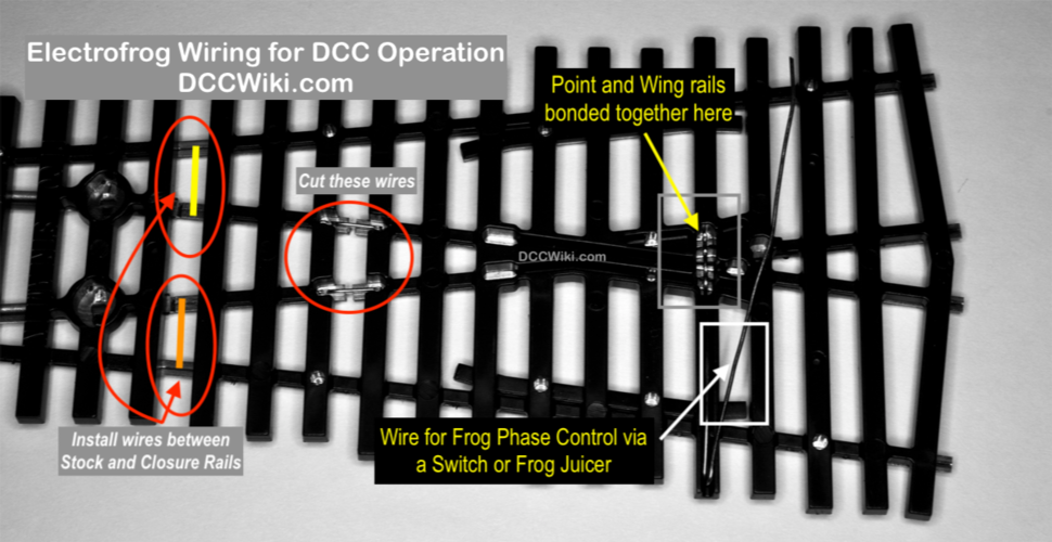
- Solder some wire bonds between the stock and its related closure rail. This restores power (with the correct phase relationships) to the closure and switch rails. There are provisions for this on the underside.
- This modification is done on the switch side of the gap.
- This serves two purposes: It supplies power to the switch rail, and makes the turnout DCC Compatible as the switch rail's phase matches the stock rail.
- Using the factory installed wire at the heel of the frog connect a Frog Juicer or a SPDT switch to power the frog. This restores power to the frog and sets up a control mechanism which maintains the correct phase relationships to the frog and point rails as a train goes through the turnout. A switch machine with contacts may also perform this function.
- It may be necessary to add the wire if it was not installed or previously removed.
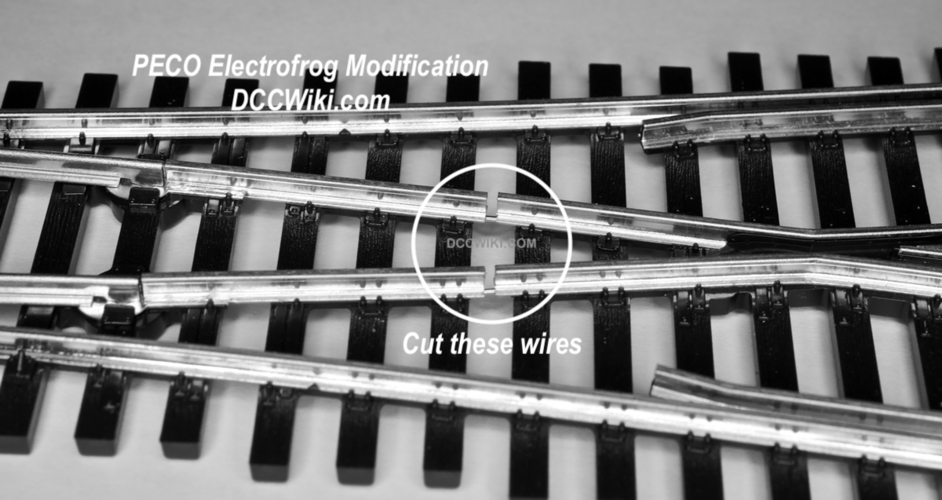
The first thing you will notice on the underside are a pair of wires bridging the gaps between the switch and closure rails. These wires bond the frog to either Rail A or B, dependant on the switch alignment. This means the switch rails are not DCC Compatible as they are both energized with the same phase through the frog via the closure rails. This makes it possible for a metal wheel to bridge between the switch rail and its adjacent stock rail.
Cut the wire bonds so that the frog's phase is no longer controlled by the switch rails. If your Electrofrog turnout is already installed, you can cut the wire bonds from the top with an Atlas snapsaw inserted into the gaps in the closure rails. This is a simple matter of snipping the wires with a pair of cutters and then twisting the wires off of the rail. They should come off very easily. You now have a "dead" frog.


Electrical View of a Modified PECO Electrofrog Turnout. The diagram shows the electrical view of a modified PECO Electrofrog in both the open and closed positions.
Contacts on switch rails and connections to the closure rails.


Preparing a Peco Electrofrog Turnout for Installation
Further Reading
- General Wiring Topics for DCC
- Types of Turnouts
- Methods of Operating Turnouts
- DCC Friendly Turnout
- Wiring Diamond Crossings, Slips, Scissor Crossings, etc.
External Links
There are a number of data sheets, in various languages, available on the PECO Technical Page. This link goes to the English Code 83 Electrofrog turnout. OO/HO Gauge Electrofrog Turnouts/Crossings (Code 83)
- ↑ Peco has begun discontinuing the Electrofrog product line. As of December 2020, the #6 Code 83 turnouts are discontinued and replaced by the SL-U8361 and SL-U8362 Unifrog.
- ↑ Most DCC boosters react to a change in current, allowing them to act on a short current spike before any damage to the booster can occur.