Hornby Zero 1
Summary: Hornby Railway's Zero1 was the first Command Control system built around a custom microcontroller from Texas Instruments. The Zero1 name was chosen to reflect that it was a Digital system. Introduced to the UK in 1979, it quickly became a dominant command control system. Unfortunately, financial issues at Hornby's parent resulted in little to no development continuing shortly after it came on the market. While Hornby did support the system for about 10 years, the Zero1 is quite robust in construction and can still be found in use today. While it is a Digital system, it is not related to nor compatible with the NMRA DCC Standard.
|
See the Video. |

Hornby Zero1
- Main article: DCC History
Hornby Railway's Zero1 was one of the first command control systems to be implemented with Digital technology. It was designed and manufactured by Hornby in the United Kingdom. The Zero1 master controller was built around a microcontroller. Even though it was discontinued after about ten years, the equipment was reportedly quite robust and could be easily repaired.
Zero1 was developed by Hornby Railways, a major manufacturer of model railroad products, unlike many of the command control makers of the time. Prior to Zero1, the only big brand name to be associated with command control was General Electric, with their ASTRAC system.
Development cost of the Zero1 is said to have been about £300,000 (£3.7 million, or US$4.9 million in today's money (2019)), a substantial sum.
System Description
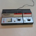
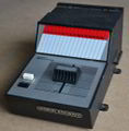
Zero1 Master and Slave units. Note the pencil tray on the master unit.
R945 Slave Unit, which attached to the Master unit. Note the 16 "slots" on the label for making notes of which engine was on that channel.
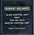
Nameplate on unit.
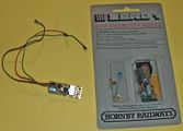
Locomotive module
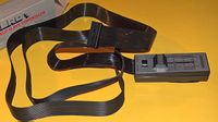
A handheld Slave Controller.


Introduced by the United Kingdom based manufacturer Hornby Railways in 1979, the United States in 1980, and to Canada in 1981. It was a digital system based around a Texas Instruments TMS1000, a four-bit microcontroller able to address and control up to 16 locomotives.
Development began in the mid 1970s. The name Zero1 was chosen to communicate that it was a digital system. Hornby management realized the declining price of digital electronics would soon make possible a digital command control system which could be manufactured and retailed at a reasonable price. Hornby began the project and received technical assistance from Texas Instruments (TI), who made custom Integrated Circuits for the system. TI introduced the first microcontroller in 1971, which made a device like the Zero1 Master Unit practical. Since everything was on one IC, design was greatly simplified. The IC contained RAM, ROM, a 4-bit microprocessor and other components of a computer all in one small package. Hornby referred to it as a mini-computer.
A primary design goal for the Zero1 was a receiver that could be fitted into most of Hornby’s products.
The Zero1 used a 32-bit code generated by the custom TI TMS1000 microcontroller[1], transmitted every third cycle of the square wave track voltage. For an 8.33-millisecond interval (60 Hz system), it replaced the track voltage. Because track power is off during transmission, the system was very resistant to interference. The code contains an identifying pulse, for up to 16 locos and 99 auxiliaries. Since Hornby was based in the United Kingdom, two different systems were made for 50 and 60 Hertz power systems which were not compatible.
The main system consisted of a Master Control Unit, R.950 (in the UK-240V 50Hz), Australian units were designated R.925 (also 240V/50Hz), US and Canadian units were designated R.944 (120V/60Hz), with up to three additional slaves (sold separately) which could be attached via a 15-pin edge connector. The throttles also offered inertia, and were capable of supplying up to 4 amps. The slaves made it easier to control multiple locomotives. Documents at the MERG Website show how one Master and 15 slaves can be daisy chained in order to achieve full independent control of 16 locomotives, each having its own controller. All sixteen engines could be in motion at the same time (if they didn't take more than 4A in total).
Upon power-up, the Master unit immediately assigned itself to address #1. Any slave units were assigned 2, 3, and 4, respectively. The master unit's keypad was used to assign decoder addresses for the slave controllers, or itself. Hornby also planned to offer the R.952 Hand Held Slave Controller, which could be used with the master/slave combination, limited to a single handheld controller, as the last in any daisy chain.
Other interesting features included user defined inertia. Since the system only had 16 speed steps, this feature made for more realistic operations. The use of a square wave, interrupted at regular intervals by data packets, resulted in noisy motor operation and poor low speed operations.
Operational Features
The Zero1 system could operate 16 locomotives, and up to 99 accessory decoders. Due to the 4-bit microprocessor used, only 16 locomotives could be on the layout, or addresses would be duplicated. Any additional locomotives would have to be stored on an electrically dead track to prevent conflicts.
Only four locomotives could be in operation at one time, and if there were slave controllers installed, their speeds could be controlled as well. With only the Master Control Unit, three would run at their previously set speeds while one was under direct control. This limitation was imposed by the 4A power supply included with the system.
Inertia could be selected and modified via the MCU's keypad. Four levels of inertia were available.
No Blocks Needed
Like DCC, the Zero1 applied its control signal to all parts of the layout, as blocks were not required to operate multiple trains. Independent control of several trains on the same section of track was possible too.
Reverse Loops
A simple DPDT switch could be used to change polarity on the loop while the train is in motion.
Locomotive Modules (Decoders)
Locomotive Module addresses (referred to as coding) were hard wired on the PCB. The user could change them, but disassembly of the locomotive was required to do that. By applying conductive paint in a specified manner, the address was set. (Soldering would damage the module.) A small vial of conductive paint was included with the decoder for this purpose. Early Locomotive Modules (up to Revision C) employed small posts and wires that were used to create the connections for the address. A small IC from TI was at the heart of the decoder
The Zero1 Locomotive Module was known to be the smallest decoder on the market, making it easy to install in many locomotives. it retailed for about £15, about £65 (US $86) today. Even at that price, it cost almost as much as a locomotive.
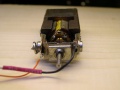
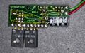
Three wires were used, two connected to the track, and one to the motor. Three wires made installation very easy, as the motor did not need to be isolated from the frame. This would make installing the module in a split-frame locomotive (very typical of Hornby designs) easier by eliminating the need to isolate the motor. By making one brush more positive (or negative) than the other, direction of travel was established. Due to the thyristor circuit used to control the motor, the system could be very erratic. The UK (50Hz) version only used a single Triac, compared to the two shown in the picture of a 60Hz North American receiver (The two triacs appeared on modules made after 1980).
The early single Triac locomotive modules were failure prone, and sensitive to noise. The two Triac type were originally marketed by Hammond and Morgan, which was later taken over by Hornby. Hornby adopted the twin triac locomotive module in 1981. The H&M digital controller was compatible with Zero1.
Hornby announced the Revision D R.965 Locomotive Module in 1981, which incorporated the conductive paint method of setting the address. The address could be changed by scraping off the paint.
Data Transmission
Data was transmitted every third pulse. The data frame consisted of a number of 4-bit nibbles. The first nibble, START, had an identification number to identify it. For accessory decoders the START nibble was 0100, for a locomotive it would be 01XX. After START, four more nibbles of data were sent, each being a locomotive instruction. Four transmissions were required to send instructions to all 16 locomotives. After the locomotive data was sent, the next four bits set the direction of each locomotive. A logical 1 meant forward, zero, reverse. Each locomotive had a bit in that nibble for direction. Then a PARITY nibble to ensure data integrity. The final data sent was a STOP nibble.
Speeds were determined by a number from 0001 (stopped) to 1111 (full throttle). The value of 0000 was not allowed. If nibbles 2 and 3 were "0000 0000", this frame was identified as one for accessory control. The next two nibbles (4 and 5) were the device address of the accessory decoder. Nibble 6 (Direction) used only the most significant bit to set the state of the accessory.
Locomotive data was sent sequentially, where accessory decoder data was only sent when it was entered on the controller. That way dirty track would not cause problems as a locomotive instruction would be sent repeatedly.
The PARITY nibble was calculated by the master controller.
Example Locomotive Frame:
The START Nibble would be 0100, 0101, 0110, or 0111. Each 34-bit data frame contained the speed and direction information for four locomotives. Four complete cycles would be needed to send all 16 locomotives their instructions. This process was repeated to ensure those locomotives had their instructions should a problem occur which interrupted data transmission. Accessory decoder data was only sent once, when the button was pressed, since intermittent data losses were less likely to occur.
For SPEED, a value of 0000 was invalid, as the accessory decoder frame used 0100 0000 0000 as the first three nibbles to identify it.
Example Accessory Decoder Frame:
Note that the first two nibbles after the START are each set to 0000, indicating that this frame of data was for the accessory decoders. The locomotive speed could never be less than 0001 as the 0000 value was reserved for the accessory decoder frame.
Locomotive Module Construction
The motor has a brush soldered to the motor frame, completing the circuit with the locomotive frame. The other wire connected to the module.
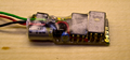
Zero1 Receiver, note lettered pads on the right side which set the channel the receiver was assigned to.
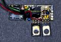
Front side of the receiver with the triacs moved aside, note the IC (black square) and the Address Pads A – D. Also note the trimmer screw above the capacitor
Reverse side of the receiver, R955 Revision D.


The locomotive module was built from several components. The main component was a microcontroller, with the address set using four lines. The track signal was supplied to it, and it used a Gate Control output to switch on the two triacs (Motorola MCR106-2) that controlled the motor. A few transistors, diodes and some resistors finished off the parts list.
The triacs were Silicon Controlled Rectifiers, which can be switched on, and will stay in that state until the polarity on the terminals is reversed. GE's ASTRAC also employed SCRs to control the motor. Speed is controlled by when the SCR is switched on, a full cycle for full speed, and a partial cycle for lower speeds. As the track power was a 20VAC signal, the SCRs would be switched off 60 times a second (50 times in the UK.) Direction was determined by which SCR was in use.
Receiver Addressing
As shown in the images, there is a set of six pads at the end of the receiver's PCB. From the factory the receiver was set to address 1 by connecting the A pad to the O pad. Any odd numbered address could be created by applying conductive paint to bridge between the lettered pads and the O pads. If an even number was desired, the trace between A and O could be cut with a knife. Any address from 1 to 16 was possible. The receiver in the image was set to address 9 (8 + 1).
Hornby discouraged using solder on the pads, stating that doing so would debond the chip and damage the receiver.
Track Power
Track power was a square wave, at about +/-20VAC. Track power came in three phases: Forward, Reverse, and Data. By controlling which of the two TRIACS mounted on the PCB was 'on', and for how long, the motor speed and direction was determined. Data was transmitted on every third cycle. No locomotive without the Zero1 receiver installed could be on the layout. The constant 20VAC track power would be harmful. The square wave was chosen for better low speed operation. A sine wave made low speed control difficult as the voltage was always changing. It was not possible to use a Zero1 equipped locomotive on a DC layout, but it was possible to wire a switch into the circuit to bypass the decoder.
Track power was transmitted at 50 or 60 Hertz, and data was transmitted at 6.6 or 13.3KHz.
Hornby also sold wire clips, or Points De-Isolating Clips (M1185) to make switches "Zero1 Friendly". (Their version of a DCC Friendly Turnout.)
Consisting
Double heading required both locos facing the same direction. The master controller merged the two locomotives into one, and was not able to determine direction individually. It was also possible to hard code two locomotive modules to the same address and use them as a consist.
Optional Power Booster
The power booster increased the Zero1's current output from 4 to 12A, so more than two Athearn diesels could be used at once. The booster retailed for $100 in 1982. A pair of 18V/4A transformers were required to provide power (not included).
Marketing
A Hornby Railways advertisement in the March 1981 issue of Model Railroader listed the American prices for a Zero1 system. The R944 Master Controller unit was $149.95, and the slaves were $49.95. A points/accessory module listed for $49.95, and the locomotive module was $24.95. (All prices in US dollars.) A later accessory was the Micro Mimic panel which could represent turnout positions using LEDs.
Hornby pricing in Canada was $219.95 for the R944 Master Controller, the R945 Slave Controller was $69.95, and the R947 "Loco Module" listed for $32.95. An R946 Accessory decoder was $69.95, which could control up to 4 switch machines. Exchange rates between the UK pound and the Canadian dollar/US dollar explain the price differences.
As the Hornby brand was not a well-known brand name in the United States, Dunbee–Combex–Marx, the owner of Hornby Railways, had to invest a lot of money marketing the Zero1 system in the US. Hornby Railways always had a larger presence in Canada, sold in major retailers such as Eatons, but delayed the rollout until 1981, a year after the US introduction. It was introduced to the UK market in 1979.
Hornby's parent company Meccano Ltd. had set up manufacturing operations in the US beginning in the 1920s, but poor sales of Meccano and Hornby products doomed the enterprise and by the late 1930s Meccano abandoned the US market. The main competition was Erector sets which were made by A.C. Gilbert, who claimed his product was not a copy of Meccano. A.C. Gilbert also made the American Flyer train sets.
Meccano continued to sell Hornby trains and Meccano sets in Canada, through small hobby shops and major retailers such as Eaton's department stores.
Over time, after acquisition and reorganizations by other companies, the Hornby brand would become the name of the company.
Hornby advertisements stated you could model a large passenger terminal with up to 16 locomotives in operation at once. Poor marketing may have limited the Zero1's appeal in the North American market, although some model railroads did use it. It was the most popular of all the command control systems in use by the mid 1980s. (Model Railroader reader surveys).
In 2021 dollars, the master unit would $460, a slave unit would be $153, and a locomotive module would cost $76.50. A Zero1 Master plus 16 locomotive modules would cost about $1700. (US Prices)
Discontinuation
In 1980 Dunbee-Combex-Marx, the company that owned Hornby Railways, was liquidated, placing Hornby Railways in receivership. This effectively ended any further development of the Zero1 system.
Hornby would discontinue the main controller unit in 1986, and by 1991 their catalog warned that supplies were limited of the R955 locomotive module. Due to parts issues, Hornby was no longer supporting Zero1 by this time.
Dunbee-Combex-Marx is still in business today manufacturing board games. In 1967 Dunbee-Combex purchased the UK operations of the Louis Marx Co. (MARX Trains), adding the Marx brand to their name. In 1975 they would purchase the remainder of the company from its owner, Quaker Oats, who took a large loss on the Marx brand they purchased in 1967. In 1971Dunbee-Combex-Marx purchased Rovex Ltd., which included Tri-ang Hornby, from the administrators of the bankrupt Lines Brothers. The company would be renamed Hornby Railways when Tri-ang was closed.
In 1980 Hornby Hobbies was created, and the company was subject to a management buyout in 1981. It would operate under this name until 2015. With further financial issues the company now called Hornby PLC was re-organized as part of a takeover by an investment group.
Other Zero1 Suppliers
Hammant and Morgan
H&M was a British supplier, known for their analog DC controllers. They also offered a Zero1 compatible system. Hornby would eventually purchase the company. H&M's Zero1 decoders were known to be better than the original Hornby units, eventually Hornby introduced an improved decoder that addressed the problems with the early design. The decoders were about 38 x 13 x 8 mm, and could supply up to one amp.
Hammant and Morgan sold their HM5000 Advanced Power Transmitter, with twin controls, and the consort controller (HM5500) for even more trains running at once. The system demanded a 6A AC power supply. The 11th Edition catalog that lists the HM5000 Advanced Power Transmitter implies that the power supply is a separate item, but the production units had the power supply built into the steel enclosure. They even included a fast clock with 4 ratios (1:1, 1:6, 1:12 and 1:24), and an audible overload alarm. The specifications stated it had two microprocessors, and was completely compatible with the Hornby Zero1. Unlike the Hornby offering, the master unit was in a metal enclosure. It featured LED displays for the locomotive addresses (and the clock) & accessories that were selected, plus an ammeter, in the catalogue it shows a horizontal moving coil ammeter, where production models had a bar graph display.
Features included the ability to display the address selected, the inertia, the last accessory decoder used, and the time, at the press of a button. Small LED indicators were lit to show what function was displayed, and were also used for indicating direction.
(Hammant and Morgan Ltd. Catalog, 1980)
MTR Services
Offered their Power Grid Systems command control system, which was compatible with the Zero1 system, in 1996.
ZTC Controls

ZTC Controls in the UK still support the system and have made improvements to it.
ZTC also makes DCC decoders that can be programmed to work with a Zero1 system, and their controllers have a mode that enables control of a Zero1 equipped locomotive.
One of the founders of ZTC was employed by Hornby as a member of the Zero1 development team. Legend says that ZTC stood for Zero Two Controller.
TMS 1000
The TMS 1000 family of 4-bit microcontrollers were introduced in 1974. They were a very simple design with only two 4-bit general registers, 43 instructions, and no interrupts. They came with 1kB of ROM onboard, and 64 X 4 bits of RAM. It had a maximum clock speed of 400 kHz.
From the Texas Instruments press release (1974):
- Lowest cost. Broadest support. PMOS, NMOS, CMOS.
- You're to market faster, and more economically, using TI's Series TMS1000 microcomputers. They carry today's lowest price. Versions are available for less than $3.00 in volume quantities. And nobody matches the depth and breadth of TI's total support that speeds design-in.
- Proven Microcomputer Family specific application requires flexibility. Which is what you get with TI's TMS1000 Series. All in the table are P-channel MOS/LSI circuits. A mature technology of proven reliability. In fact, TI has more than six years of experience in building millions of PMOS devices.
- Reliability is enhanced by single-chip construction that cuts component count as much as 75% - which helps hold total system costs down.
- Soon to come: NMOS circuits for faster throughout and CMOS microcomputers for applications requiring low-voltage, low-power operation.
The TMS1000 and its variations powered thousands of calculators, as well as microwave ovens and other electronic devices, including the Speak and Spell toy
The $3 cost (in quantity, about $15 in 2021) made the IC very attractive to Hornby's Zero1 Design Team as it was a low-cost device which eliminated a lot of components in the process, making the product cheaper. Today, a microcontroller can be had for less than a $1 in quantity.
Return to the DCC History page
Zero1 Video
Notes
- Phase 1 Locomotive Control
- Phase 2 Accessory Control
- Phase 3 Micromimic Display
It seems that the extra ports on the rear of the R.958 Phase 3 Micromimic Display Console were never utilised, the Display console also had buttons marked ERASE, REWRITE, MEMORY and ROUTE, with a lid at the rightmost, on the rear were two ports marked RAILDRIVE and LIGHTPEN, these have no known function. Commentators regularly speculate that these ports may have been Phase 4 and 5, if development continued.
See Also
External Links