Chuff Cam
Summary: A device for triggering sound effects heard during the operation of an external combustion locomotive.

Chuff Cam
A Chuff Cam is a cam used with a sound decoder to control the beat of a steam locomotive.
The "beat" is the sound heard as the pistons move, exhausting steam into the blast pipe. The blast pipe is a device positioned below the stack in the smokebox, whose purpose is to provide draft for the fire. Steam exhausted through the stack via the blast pipe provides the draft. Nozzles are used to direct the steam up the stack, propelling combustion gases out of the smokebox in the process.
The chuff cam is used with a wiper to complete an electrical circuit. Sound decoders may be fitted with a wire for this purpose. The cam is installed on an axle, and the wiper is positioned to make or break the circuit. Other methods may use a small disk mounted on the axle against the back of one driver.
It is similar in concept to the ignition systems used in automobiles prior to the advent of electronic ignition. The high voltage was created by opening a switch, (the points) which was actuated by a small cam driven by the camshaft. This timed the spark correctly. The number of lobes on the cam depends on the number of cylinders, such as 4, 6 or 8.
See here for more information on mechanically timed ignition systems. In this application, poor adjustment may result in engine pinging, poor performance, or an engine that will not run (or maybe even backfire during starting.) None of these problems appear in DCC.
The purpose of a chuff cam is to synchronize the beat (or chuffs) with the rotation of the wheels. Most sound decoders have an autochuff feature, which controls the beat using a combination of things, such as motor voltage, back EMF, and throttle settings/changes. Problem is, it is guessing as to the rate the valves would be operating, and as a result, it may not be realistic.
A steam locomotive has 4 beats per wheel revolution. The cam will lock the rate to the revolution of the wheel. Thus, the beat is directly related to the speed of the locomotive. Which means the sound is more realistic than that achieved by using autochuff.
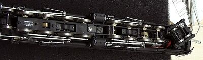
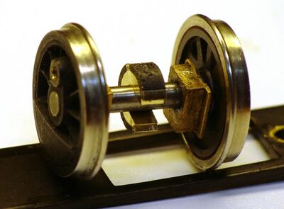
Brass chuff cams mounted on the axles of articulated locomotive.
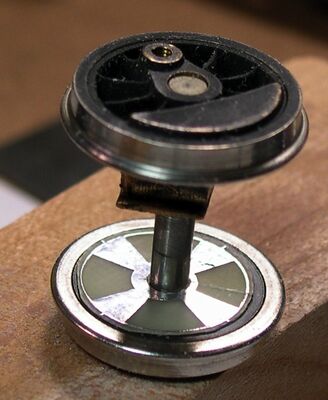
Soundtraxx chuff cam, installed on axle.
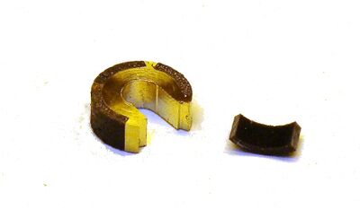
GME chuff cam


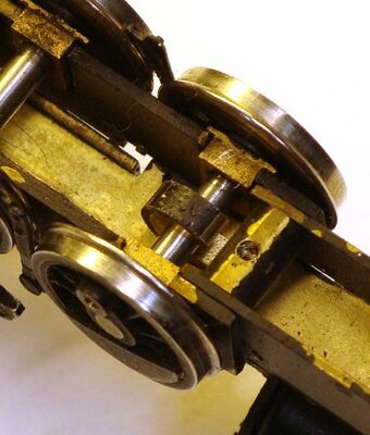
The picture shows a chuff cam (the brass object) mounted on an axle. As this is an articulated locomotive, it has two cams, with four lobes, one for each engine. The cam is electrically live, and the wiper touches one of the four lobes for each revolution, connecting the voltage to the decoder. The decoder interprets that to mean "chuff". A plate is removed on the rear engine, showing the axles, bearings, gearbox, and of course, the cam on the third axle.
Articulated engines have another issue: the two engines will move in and out of sync due to slippage. Soundtraxx has a "slip" feature included in the Tsunami decoder when in "auto exhaust" mode. With cams, that will not happen. Since both engines are driven off the same driveshaft, they cannot operate at different speeds.
The Tsunami will revert to "auto exhaust" when operated in analog mode, as it needs the digital signal found on DCC systems to function.
A chuff cam will add realism to your external combustion motive power.
Installing a Chuff Cam
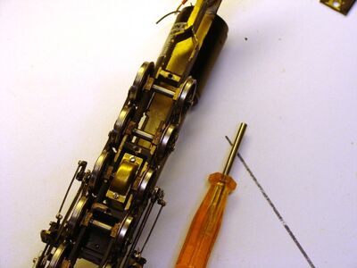
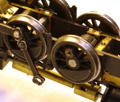
Drivers with belly pan removed and the special wrench for the crank pins.
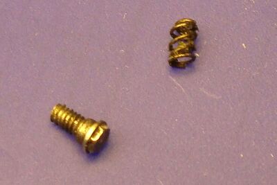
Don't lose the springs or the crankpins!


This will use a Grizzly Mountain Engineering cam as an example.
The first step is to remove the belly pan to gain access to the axles.
Mark one bearing so you can reinstall it properly. (Since the wheels are quartered, they must go back exactly the same way.)
In this example, the crank pins are removed using a special socket driver included with the locomotive. Gently remove the crank pins. Forcing things can damage the tool, the screw head, or both. ONLY REMOVE THE WHEELSET YOU PLAN TO INSTALL A CAM ON! Leave as much of the reciprocating assembly in place as possible. Less things to lose, or misalign later.
Lift the wheelset out. Pay attention, as many will have sprung drivers and you don't want to lose a spring.
Test Fit
Cam installed on the axle prior to test fitting and bonding.
Another view of the axle, checking clearances.
Cam installed.
Axle polished prior to bonding.


In this case the cam slid onto the axle without a lot of effort. Carefully align and install the driver set and check for any interference. Solve those problems before proceeding.
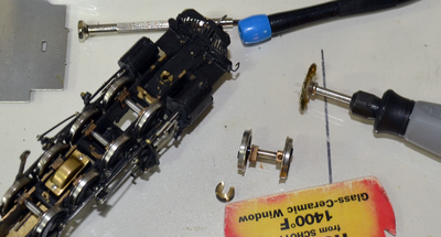
In this example a part of the frame will interfere with the cam. This will not do, so the solution is to mount an end mill in a Dremel tool, and remove some material. The idea is to make clearances for the cam without sacrificing the threaded hole used to fasten the belly pan at this point.
Installation
Follow the manufacturer's instructions. GME recommends preparing the surface with a fine sandpaper, the epoxy the cam in place and set aside to dry. After the epoxy has cured, fit the spacer into the cam, and when it fits correctly, epoxy it into place. After curing, trim any excess epoxy off. In this example, conductive epoxy will be employed, and the axle polished with a brass wire brush mounted in a Dremel tool. The epoxy contains silver and is used in the electronics industry in place of soldering. Don't bother to fit the plastic spacer until later.
The Soundtraxx Chuff Cam:
The connection to the axle is made with conductive paint, such as that used for repairing circuit boards. They recommend buying a cam designed for soldering if you wish to take that route. Conductive paint, often called "Nickel Print", can be used to complete the circuit.
See also
- Sound - The page about Sound
- Decoders More info on decoders
- Specific_decoder_installs Specific Decoder Installs.